Sync-output system and sync-output method for triaxial fiber optic gyros

A fiber optic gyroscope, X-axis technology, applied in Sagnac effect gyroscope and other directions, can solve the problems of low precision, poor output synchronization of three-axis fiber optic gyroscope, poor real-time performance, etc., to ensure synchronization and integrity, improve inertial Real-time performance and accuracy, and the effect of improving computing power

Active Publication Date: 2016-03-02
CHONGQING HUAYU ELECTRIC GRP
View PDF6 Cites 5 Cited by
  • Summary
  • Abstract
  • Description
  • Claims
  • Application Information

AI Technical Summary

Problems solved by technology

[0003] In view of the above-mentioned deficiencies in the prior art, the purpose of the present invention is to solve the problems of poor output synchronization of existing three-axis fiber optic gyroscopes, resulting in poor real-time performance and low precision of inertial navigation, and to provide a three-axis fiber optic gyroscope synchronous output system and synchronous output method. It can ensure the output synchronization of the three-axis fiber optic gyroscope, thereby improving the real-time and accuracy of inertial navigation

Method used


Image

  • Sync-output system and sync-output method for triaxial fiber optic gyros
  • Sync-output system and sync-output method for triaxial fiber optic gyros

Examples


Embodiment

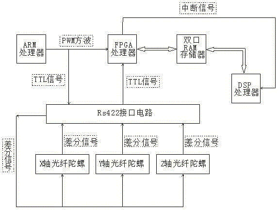
[0022] Example: see figure 1 , a three-axis fiber optic gyroscope synchronous output system, including an X-axis fiber optic gyroscope, a Y-axis fiber optic gyroscope, a Z-axis fiber optic gyroscope, an ARM processor, an FPGA processor, a double-pull RAM memory, and a DSP processor; during specific implementation, the The ARM processor is an STM32F407IC type processor, the FPGA processor is an XC6SLX45 type processor, the DSP processor is a TMS320C6713 type, and the dual-port RAM memory is a 48LC8M16A2 type memory.

[0023] The ARM processor can output a PWM square wave, and a timer of the ARM processor and its corresponding output channel are used as a PWM output port, so that the output timing can be controlled. One of its (PWM square wave) output ports is directly connected to the FPGA processor, and the other is connected to the TTL pin of the RS422 interface circuit. The PWM square wave signal is converted into a differential signal by the RS422 interface circuit. The dif...


PUM


Abstract

The invention discloses a sync-output system and a sync-output method for triaxial fiber optic gyros. The sync-output system comprises an X-axis fiber optic gyro, a Y-axis fiber optic gyro, a Z-axis fiber optic gyro, an ARM processor, an FPGA processor, a double-interface memorizer, and a DSP. The sync-output method comprises the following steps: 1) the ARM processor generates a PWM square wave; 2) the x-axis fiber optic gyro, the Y-axis fiber optic gyro and the Z-axis fiber optic gyro output differential signals respectively; 3) angular velocity data received by the FPGA processor are saved into the double-interface memorizer; 4) the FPGA processor sends an interrupt signal to the DSP; 5) the DSP reads the angular velocity data and calculates the angular velocity data. The sync-output system and the sync-output method have the advantage that the output synchronicity of the three axial fiber optic gyros can be guaranteed, so as to improve inertial navigation and precision.

Description

technical field [0001] The invention relates to the technical field of inertial navigation equipment, in particular to a three-axis optical fiber gyro synchronous output system and a synchronous output method. Background technique [0002] In recent years, with the development of technology, fiber optic gyroscopes are gradually replacing flexible gyroscopes and are widely used in the field of navigation equipment. The traditional flexible gyroscope uses analog signal output, and it needs to design complex excitation and sampling circuits to perform analog-to-digital conversion to obtain the angular velocity of the carrier. The accuracy is low; the fiber optic gyroscope has high accuracy, but it uses digital signal output. While reducing the peripheral sampling circuit, it also brings a new problem, that is, the control problem of the gyro output timing. The commonly used blind transmission mode output will cause the three-axis gyro data output time to be out of synchroniz...

Claims


Application Information

Patent Timeline
Patent Type & Authority Applications(China)
IPC IPC(8): G01C19/72
CPCG01C19/72
Inventor 刘源吴金伟
Owner CHONGQING HUAYU ELECTRIC GRP
Why Eureka
Try Eureka