
Automatic film laminating mechanism for film laminating machine

A technology of laminating mechanism and laminating machine, applied in ceramic molding machines, auxiliary molding equipment, metal processing, etc., can solve the problems of many power devices, film damage costs, and inability to directly complete lamination, lamination and film cutting, etc. , to achieve the effect of high degree of automation, stable transmission and good attachment effect

Active Publication Date: 2020-05-15
万金芬
View PDF6 Cites 0 Cited by
  • Summary
  • Abstract
  • Description
  • Claims
  • Application Information

AI Technical Summary

Problems solved by technology

[0005] The purpose of the present invention is to address the deficiencies of the prior art, by setting up a turnover mechanism to cooperate with the film feeding mechanism to complete the automatic film covering of prefabricated plates, and after film covering, the film cutting mechanism can be used to automatically cut, and then cooperate with the film pressing mechanism , can automatically press the coated film so that the film is tightly attached, the attachment effect is good, and it is beneficial to the maintenance of the prefabricated board, thus solving the problem that the three operations of film lamination, film pressing and film cutting cannot be directly completed on the laminating machine , and there are too many power devices, it is easy to cause film damage due to misoperation and high cost technical problems

Method used


Image

  • Automatic film laminating mechanism for film laminating machine
  • Automatic film laminating mechanism for film laminating machine
  • Automatic film laminating mechanism for film laminating machine

Examples


Embodiment 1

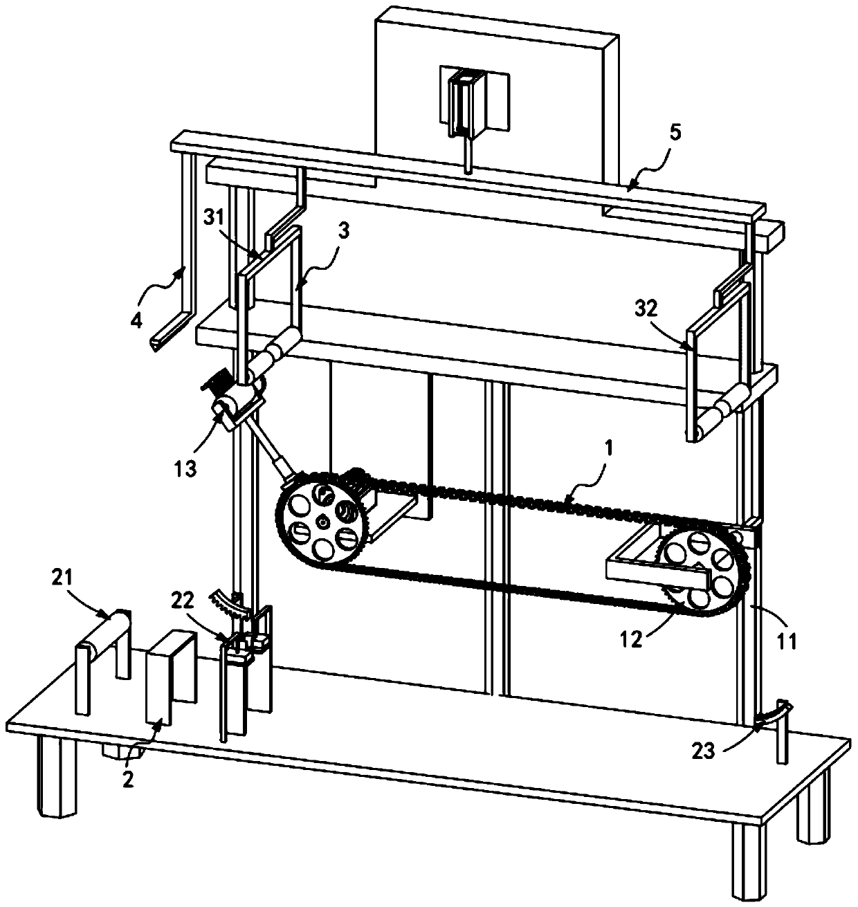
[0062] like figure 1 , Figure 9 and Figure 10 As shown, the automatic laminating mechanism for the laminating machine includes:

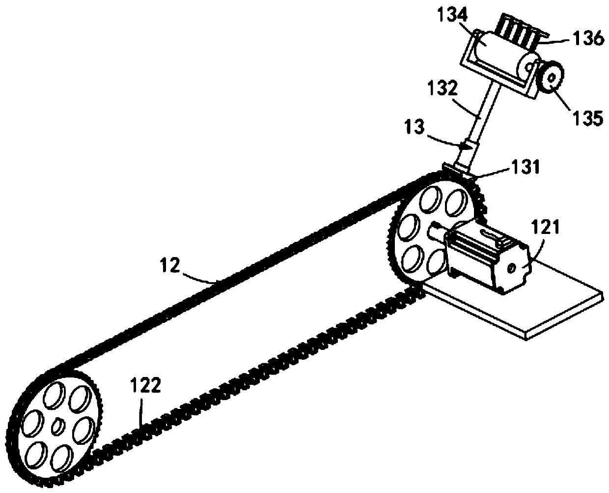
[0063] A revolving mechanism 1, the revolving mechanism 1 includes a first drive assembly 12 installed on the frame 11 and a film pulling assembly 13 driven by the first drive assembly 12 to rotate;

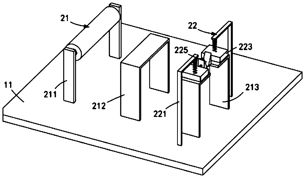
[0064] The film feeding mechanism 2, the film feeding mechanism 2 includes a film feeding assembly 21 arranged on the frame 11 and located on one side of the first drive assembly 12, arranged above the film feeding assembly 21 and connected to the film feeding assembly 21 The limiting assembly 22 of the film pulling assembly 13 intermittent contact and the film releasing assembly 23 arranged on the other side of the first driving assembly 12 relative to the film feeding assembly 21;

[0065] A film pressing mechanism 3, which includes a first film pressing assembly 31 arranged on one side of the film feeding assembly 21 and a second film pressing ...

Embodiment 2

[0110] like Figure 8 , Figure 9 and Figure 10 As shown, the components that are the same as or corresponding to those in the first embodiment are marked with the corresponding reference numerals in the first embodiment. For the sake of simplicity, only the differences from the first embodiment will be described below. The difference between this embodiment two and embodiment one is:

[0111] Further, the second drive assembly 5 includes:

[0112] A pneumatic part 51, the pneumatic part 51 is arranged above the epicyclic mechanism 1 and its telescoping end is arranged vertically downward; and

[0113] The load bearing plate 52 is in transmission connection with the pneumatic component 51 and is arranged horizontally.

[0114] It is worth mentioning here that a sensor is provided on the film release assembly 23. When the film pulling assembly 13 reaches the film release assembly 23, the sensor senses and sends a signal to the second drive assembly 5, and the pneumatic for...


PUM


Abstract

The invention relates to an automatic film laminating mechanism for a film laminating machine. The automatic film laminating mechanism comprises a turnover mechanism, a film feeding mechanism, a filmpressing mechanism and a film cutting mechanism, wherein the revolving mechanism comprises a first driving assembly mounted on a rack and a film drawing assembly driven by the first driving assembly to revolve; the film feeding mechanism comprises a film feeding assembly, a limiting assembly which is arranged above the film feeding assembly and intermittently makes contact with the film drawing assembly, and a film releasing assembly arranged on the other side of the first driving assembly relative to the film feeding assembly; the film pressing mechanism comprises a first film pressing assembly arranged on one side of the film feeding assembly and a second film pressing assembly arranged on one side of the film releasing assembly, and the film pressing mechanism is linked with the film releasing operation of the film releasing assembly through a transmission mechanism; and the film cutting mechanism is connected with the film pressing mechanism and is used for cutting film tails. Theautomatic film laminating mechanism for the film laminating machine solves the technical problems that the three operations of film laminating, film pressing and film cutting cannot be directly completed on the film laminating machine, too many power devices are arranged, so that films are damaged easily due to misoperation, and the cost is high at the same time.

Description

technical field [0001] The invention relates to the technical field of laminating machines, in particular to an automatic laminating mechanism for a laminating machine. Background technique [0002] Prefabricated concrete components are building components prefabricated in factories with concrete as the basic material, including beams, slabs, columns and building decoration accessories. After the concrete is poured and tamped, it will gradually set and harden, mainly due to the hydration of the cement, and the hydration requires appropriate temperature and humidity conditions. Therefore, in order to ensure that the concrete has suitable hardening conditions and its strength continues to grow, it must Concrete is cured. The more commonly used curing method is to apply film on concrete structures or components. That is, after the initial setting of the concrete and before the final setting, the concrete curing film is paved to make the concrete curing film closely adhere to ...

Claims


Application Information

Patent Timeline
IPC IPC(8): B28B11/24B28B17/00B26D1/06
CPCB26D1/065B28B11/245B28B17/00
Inventor 钱丽峰
Owner 万金芬
Learn More