Prefabricated finished cable trench

A technology of finished cables and cable trenches, which is applied in the installation of cables and ground cables, etc., which can solve the problems of unfavorable maintenance and maintenance work, complicated operation procedures, and large depth of soil layers, so as to achieve flexible and changeable matching methods and avoid stress Damage, reducing the effect of engineering difficulty

Inactive Publication Date: 2017-12-26
STATE GRID CORP OF CHINA +1
View PDF13 Cites 10 Cited by
  • Summary
  • Abstract
  • Description
  • Claims
  • Application Information

AI Technical Summary

Problems solved by technology

The disadvantages of this structure are: the whole structure is arranged vertically, the depth of the soil layer that needs to be excavated is relatively large, and multiple cable supports are arranged vertically, which is not conducive to the follow-up maintenance work
Although this structure reduces the cost in the factory prefabrication process, it needs to preassemble two prefabricated parts when making on-site assembly, the operation procedure is complicated, and the size of the combined cable trench is unique, which cannot meet the needs of different places.

Method used


Image

  • Prefabricated finished cable trench
  • Prefabricated finished cable trench
  • Prefabricated finished cable trench

Examples


Embodiment 1

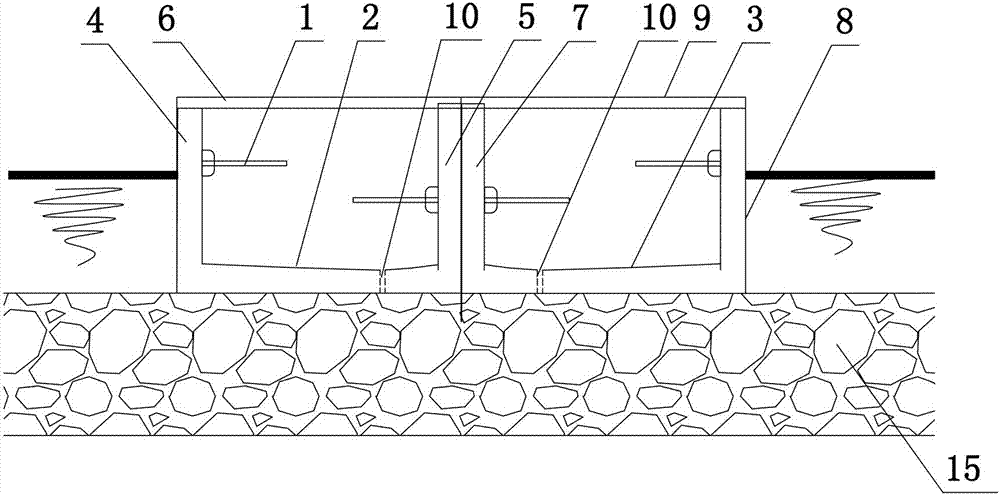
[0039] Such as Figure 1 to Figure 4 As shown, the present invention includes a plurality of cable trench monomers and a crushed stone permeable drainage layer 15 laid below the cable trench, a cable support 1 arranged in the cable trench monomer, and the cable trench monomer includes a prefabricated module fixedly connected to the first trench wall and For the second ditch wall prefabricated module, the gap between the first ditch wall prefabricated module and the second ditch wall prefabricated module is sealed by pouring mortar, and the joints between multiple cable trenches are sealed and fixed by mortar filling;

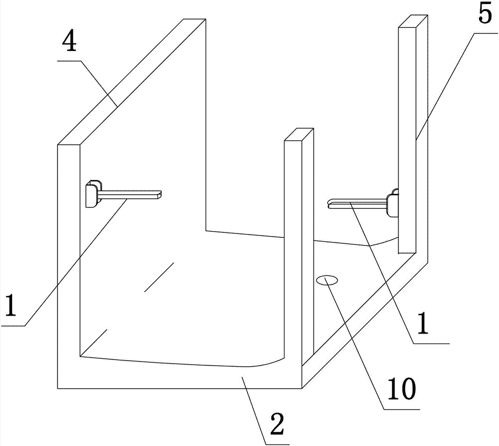
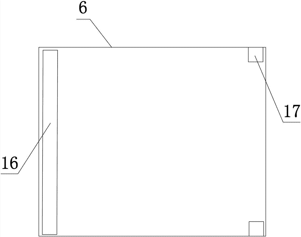
[0040] The first ditch wall prefabricated module includes the first bottom plate 2 and the first ditch wall 4 and the first square steel group 5 integrally formed on the first bottom plate 2. The upper ends of the first ditch wall 4 and the first square steel group 5 are installed with the first A cover plate 6, the lower end surface of the first cover plate 6 i...

Embodiment 2

[0045] The structure of this embodiment is basically the same as that of Embodiment 1, the difference is: as Figure 5 to Figure 7 As shown, one or more intermediate prefabricated modules are added between the first ditch wall prefabricated module and the second ditch wall prefabricated module. The third-party steel group 12 and the fourth-party steel group 13. In this embodiment, a third bottom plate 11 is used as an example for illustration. The third bottom plate 11 is installed between the first bottom plate 2 and the second bottom plate 3 using a reinforced concrete structure. The third-party steel group 12 and the fourth square steel group 13 are pre-buried on the upper end surface of the first bottom plate 11, and the upper ends of the third-party steel group 12 and the fourth square steel group 13 are provided with a third cover plate 14, and the third cover plate 14 The lower end surface is provided with a square groove 17 that engages with the third-party steel group...

Embodiment 3

[0047] The structure of this embodiment is basically the same as that of Embodiment 2, the difference is that: the cable support 1 is provided with an arc-shaped bending portion 18, and the arc of the arc-shaped bending portion 18 is less than 180°; Support rod 19, the other end of support rod 19 is connected with the first ditch wall 4, the second ditch wall 8 or square steel, as Figure 8 As shown, the prefabricated module of the first ditch wall is taken as an example for illustration. In the actual production process, the support rod 19 on the first ditch wall 4 is pre-embedded in the same way as the cable support 1. The first square steel group 5 The upper support rod 19 is fixed by bolts, and the structure of the second ditch wall prefabricated module and the middle module is similar to that of the first ditch wall prefabricated module, which will not be repeated here.

[0048] In the structural design of this embodiment, when in use, the arc-shaped bending part 18 is us...


PUM


Abstract

The invention belongs to the technical field of cable facilities in transformer substations, and particularly relates to a prefabricated finished cable trench. The prefabricated finished cable trench comprises a plurality of cable trench bodies and cable holders in the cable trench bodies. Each cable trench body comprises a first base plate and a second base plate which are connected fixedly. First trench walls and first square steel sets are arranged on the upper end faces of the first base plates from left to right. First cover plates are arranged at the upper ends of the first trench walls and the first square steel sets. Second square steel sets and second trench walls are arranged on the upper end faces of the second base plates. Second cover plates are arranged at the upper ends of the second squire steel sets and the second trench walls. The prefabricated finished cable trench has the advantages that the longitudinal depth design of conventional cable trenches is changed into flattening design, so that on the premise of guaranteeing utilization rate of cable channel sections, construction difficulty in laying of cables is reduced, and convenience is brought to follow-up maintenance and operation; multiple prefabricated modules are matched flexibly to splice cable trenches with different widths, and the prefabricated finished cable trench is applicable to cable laying at different places.

Description

technical field [0001] The invention belongs to the technical field of cable facilities in substations, in particular to a prefabricated cable trench. Background technique [0002] The cable trench is an openable underground channel for laying cables, including a bottom plate, a side wall on the bottom plate, a cover plate on the side wall, and cables and cable terminal boxes are laid in the cable trench. Current situation analysis of cable trench: [0003] 1. Traditional cable trenches. This type of cable trench is generally a brick structure or cast-in-place concrete structure. It continues to purchase sand, bricks, steel bars, cement and other construction materials on site, and binds steel bars, erects formwork, and mixes concrete on site. , pouring, maintenance, masonry filling walls and painting and other traditional modes, the traditional cable trench has many deficiencies in the production process, such as the low strength of the brick cable trench, the heavy labor ...

Claims


Application Information

Patent Timeline
Patent Type & Authority Applications(China)
IPC IPC(8): H02G9/02
CPCH02G9/02
Inventor 姚晗刘湘莅孟凡斌陈晨樊庆玲张清峰姚若夫郝健张亚婷李恒程颖颖郭静宋景博郑泞康宋文卓张亮汪赟申燕飞
Owner STATE GRID CORP OF CHINA
Why Eureka
Try Eureka