Cloth roll taking and changing mechanism

A technology of cloth rolls and pallets, which is applied in the direction of winding strips, thin material handling, transportation and packaging, etc., can solve the problems of low efficiency, troublesome operation, and placing the cloth roll mandrel in place, so as to save manpower and material resources, High efficiency, easy replacement of cloth

Pending Publication Date: 2020-05-15
CHONGQING TENWAYS MATERIAL CORP
View PDF0 Cites 0 Cited by
  • Summary
  • Abstract
  • Description
  • Claims
  • Application Information

AI Technical Summary

Problems solved by technology

[0002] In the electronic grade glass fiber cloth manufacturing industry, glass fiber cloth usually needs to be desized twice after weaving. After the first desizing, in order to better perform the second desizing, it needs to be rolled into a roll with a perforated mandrel, which is often used for rolling cloth. The mandrel is usually larger in size and heavier in weight. In the prior art, when the mandrel is replaced by a cloth roll, it is necessary to use a crane to lift the mandrel to the position of the cloth rolling machine, and then place it on the cloth rolling machine for use. When using a driving machine, the operation is cumbersome, the efficiency is not high, and it is difficult to accurately place the cloth roll mandrel in place, so it is necessary to design a faster and more effective tool

Method used


Image

  • Cloth roll taking and changing mechanism
  • Cloth roll taking and changing mechanism
  • Cloth roll taking and changing mechanism

Examples


Embodiment Construction

[0016] The present invention will be described in further detail below in conjunction with specific embodiments and accompanying drawings.

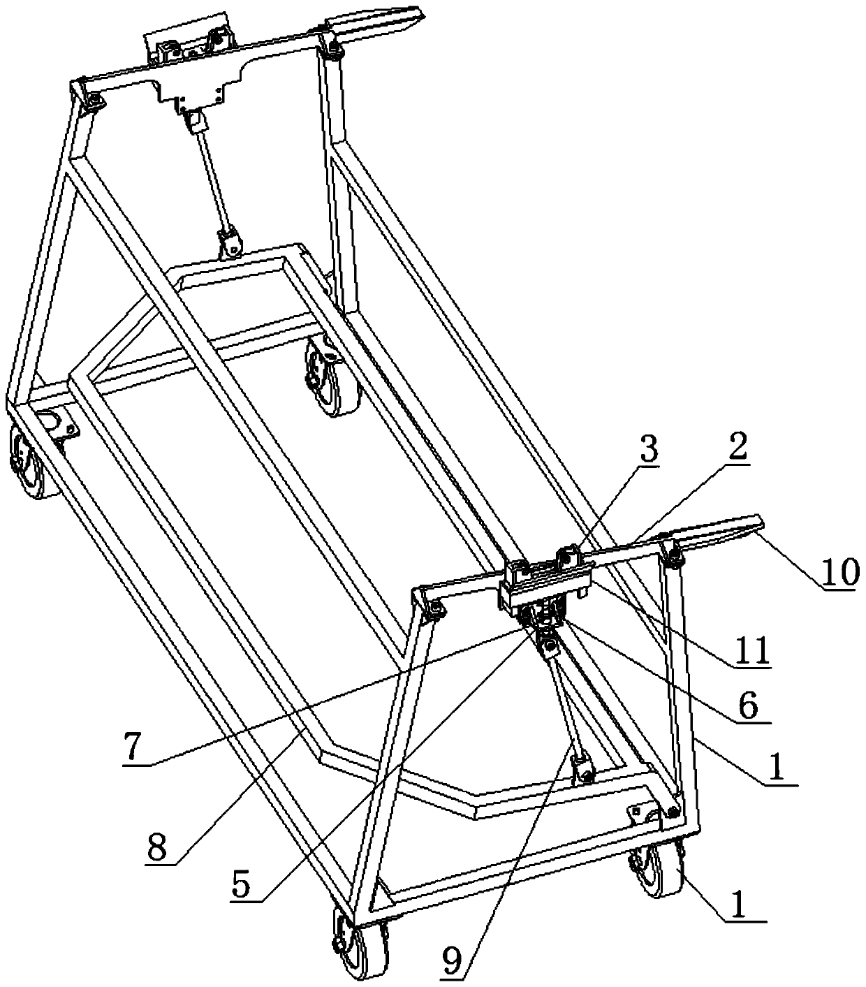
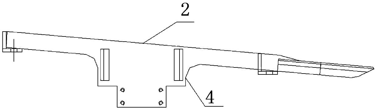
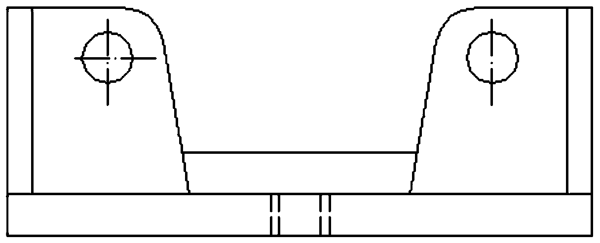
[0017] a kind of like Figure 1-3 The cloth roll taking and changing mechanism shown includes a vehicle frame 1, which has two supporting surfaces, front and rear, wherein the height of the rear supporting surface is higher than that of the front supporting surface. The top of the vehicle frame 1 has a supporting plate 2 connected from the rear supporting surface to the front supporting surface, the number of the supporting plates 2 is two, and they are respectively located at both ends of the top of the vehicle frame 1 . The two supporting plates 2 are arranged in parallel, and each of the supporting plates 2 is inclined from the rear supporting surface to the front supporting surface. Under the action, it will automatically roll along the supporting plate 2. The middle part of the supporting plate 2 is provided with a vertically movab...


PUM


Abstract

The invention discloses a cloth roll taking and changing mechanism. The cloth roll taking and changing mechanism is characterized in that a frame is included and provided with a front supporting faceand a rear supporting face, wherein the height of the rear supporting face is larger than that of the front supporting face; the top of the frame is provided with two supporting plates connected to the front supporting face from the rear supporting face, and the two supporting plates are located at the two ends of the top of the frame correspondingly; and the two supporting plates are parallelly arranged, the top faces of the supporting plates are provided with straight sliding rails, the middles of the supporting plates are provided with vertically-moving lifting bearing seats, during ascending, the lifting bearing seats are higher than the top faces of the supporting plates, during descending, the lifting bearing seats are completely located below the top faces of the supporting plates,notches of cloth roll spindles are limited in the middles of the lifting bearing seats, and the frame is provided with a stepping mechanism for driving the lifting bearing seats to ascend and descend.The cloth roll taking and changing mechanism has the beneficial effects that cloth taking and changing of a cloth rolling machine are easier, the efficiency of changing cloth rolling cores is higher,and manpower and material resources are greatly saved.

Description

technical field [0001] The invention relates to the field of auxiliary tools for taking and changing a mandrel for cloth rolls, in particular to a cloth roll taking and changing mechanism. Background technique [0002] In the electronic grade glass fiber cloth manufacturing industry, glass fiber cloth usually needs to be desized twice after weaving. After the first desizing, in order to better perform the second desizing, it needs to be rolled into a roll with a perforated mandrel, which is often used for rolling cloth. The mandrel is usually larger in size and heavier in weight. In the prior art, when the mandrel is replaced by a cloth roll, it is necessary to use a crane to lift the mandrel to the position of the cloth rolling machine, and then place it on the cloth rolling machine for use. When using a driving machine, the operation is cumbersome, the efficiency is not high, and it is difficult to accurately place the cloth roll mandrel in place, so it is necessary to des...

Claims


Application Information

Patent Timeline
IPC IPC(8): B65H19/30
CPCB65H19/30
Inventor 伏健何键王晨光
Owner CHONGQING TENWAYS MATERIAL CORP
Why Eureka
Try Eureka