Pipe jacking model test device

A model test device and pipe jacking technology, which is applied in the direction of measuring devices, machine/structural component testing, instruments, etc., can solve the problems of low reuse rate, fixed size, waste, etc., and achieve reasonable design, accurate testing, and easy The effect of the operation

Inactive Publication Date: 2020-05-15
WUHAN UNIV OF SCI & TECH
View PDF7 Cites 4 Cited by
  • Summary
  • Abstract
  • Description
  • Claims
  • Application Information

AI Technical Summary

Problems solved by technology

However, at present, the size of the model box for the pipe jacking model test is mostly customized, and the size is fixed. Generally, a single-sized model box can only simulate one working condition, and the reuse rate is not high, resulting in unnecessary waste.

Method used


Image

  • Pipe jacking model test device
  • Pipe jacking model test device
  • Pipe jacking model test device

Examples


Embodiment Construction

[0024] The principles and features of the present invention are described below, and the examples given are only used to explain the present invention, and are not intended to limit the scope of the present invention.

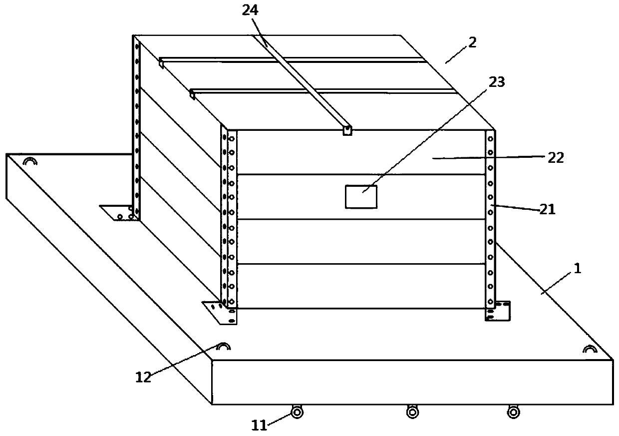
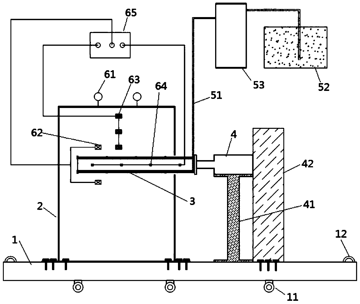
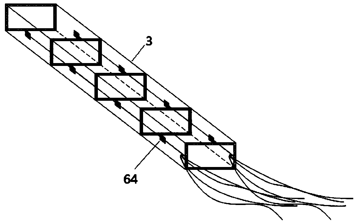
[0025] Example: such as figure 1 with 2 As shown, the pipe jacking model test device of this embodiment includes a test bench 1, a spliced ​​test box 2, a pipe jacking model 3, a lateral loading device 4, a grouting system and a data acquisition system. The above spliced ​​test box 2 is assembled in a horizontal The upper end of the above-mentioned test bench 1 provided is open, and a model soil body is housed inside, and the side wall of the above-mentioned spliced ​​test box 2 is provided with an inlet and outlet 23 for the above-mentioned pipe jacking model 3 to enter and exit. The above-mentioned pipe jacking model 3 is It is composed of multi-section pipes butted and assembled in sequence, and a grouting port 31 is provided at the joint of two adjacent pi...


PUM


Abstract

The invention discloses a pipe jacking model test device. The device comprises a test bed, a spliced test box, a pipe jacking model, a transverse loading device, a grouting system and a data acquisition system. The spliced test box is assembled at the upper end of a horizontally arranged test bed. The upper end of the spliced test box is open, and the spliced test box is internally provided with amodel soil body. The side wall of one side of the spliced test box is provided with an entrance for the pipe jacking model to enter and exit. The pipe jacking model is formed by sequentially buttingand assembling a plurality of sections of pipe bodies. A grouting opening is formed in the splicing position of every two adjacent pipe bodies. The jacking pipe model is horizontally arranged, one endof the jacking pipe model enters the model soil body from the inlet and outlet, the transverse loading device is in transmission connection with the other end of the jacking pipe model and used for horizontally pushing the jacking pipe model into the model soil body, a grouting pipe of the grouting system stretches into the jacking pipe model from the other end of the jacking pipe model, and eachgrouting opening is provided with a grouting branch pipe in a communicating mode. The device has the advantages of being high in simulation degree, capable of accurately testing soil settlement and internal pressure changes in the jacking process of the jacking pipe, and accurate in test data.

Description

technical field [0001] The invention relates to the field of underground geotechnical engineering tests, in particular to a model test device for pipe jacking. Background technique [0002] The pipe jacking construction uses the pipe jacking machine to cut the soil, and uses the thrust of the main jacking cylinder or the relay station between the pipelines to push the pipe jacking machine and the pipeline forward one by one, realizing the green, safe and environmentally friendly non-excavation construction of pipeline laying technology. As one of the main technologies of trenchless construction, pipe jacking construction technology has been widely used in underground parking lots, underground common trenches, tunnels passing through urban roads, subway entrances and exits, street crossing underground passages, and urban underground commercial space development. [0003] The pipe jacking construction breaks the original stress balance of the soil, changes the stress-strain s...

Claims


Application Information

Patent Timeline
Patent Type & Authority Applications(China)
IPC IPC(8): G01M99/00
CPCG01M99/00
Inventor 徐从军龚建伍
Owner WUHAN UNIV OF SCI & TECH
Why Eureka
Try Eureka