Foundation pile self-balance detection device with internal grouting function

A detection device and self-balancing technology, which are used in infrastructure engineering, infrastructure testing, construction, etc., can solve problems such as potential safety hazards, uneven stress on foundation piles, and inability to properly relieve pressure, and achieve reliable test results. The effect of accurate settlement and complete integrity

Inactive Publication Date: 2017-03-22
NANCHANG YONGQI TECH DEV
View PDF4 Cites 2 Cited by
  • Summary
  • Abstract
  • Description
  • Claims
  • Application Information

AI Technical Summary

Problems solved by technology

In this scheme, a single oil pipe structure is adopted, and it is impossible to accurately judge whether the load box is in normal working condition
Using hydraulic oil as the loading body, because the hydraulic oil cannot be integrated with the concrete, it is impossible to perform secondary grouting inside the device, posing safety hazards
After the load box is loaded, the pressure cannot be released properly, the foundation pile cannot rebound properly, and the settlement measured by the displacement sensor is not accurate
Assembled on-site without overall verification, the safety and accuracy of foundation pile detection cannot be guaranteed
Multi-cylinder structure, uneven force on foundation piles; for foundation pile detection with small pile diameter and large ultimate bearing capacity, there is no internal pressurization device, the grout pipe cannot pass through the load box, and the sediment and laitance cannot be discharged smoothly, resulting in pile failure. Segregation and other phenomena

Method used


Image

  • Foundation pile self-balance detection device with internal grouting function
  • Foundation pile self-balance detection device with internal grouting function
  • Foundation pile self-balance detection device with internal grouting function

Examples


Embodiment Construction

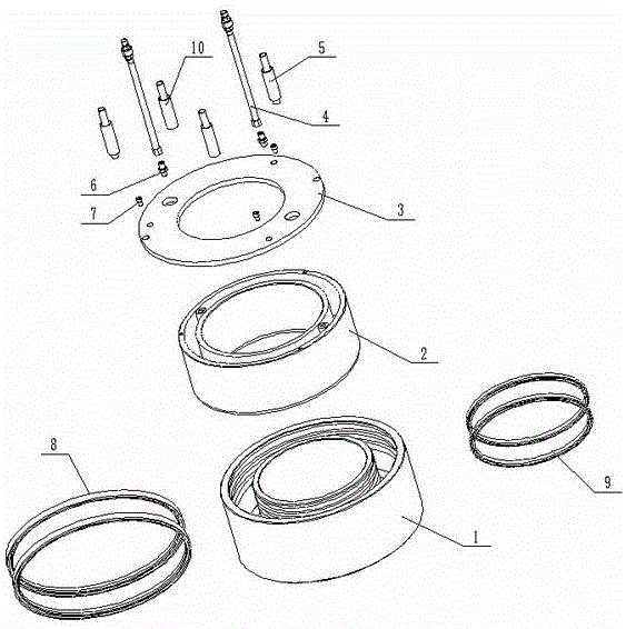
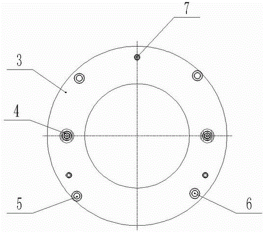
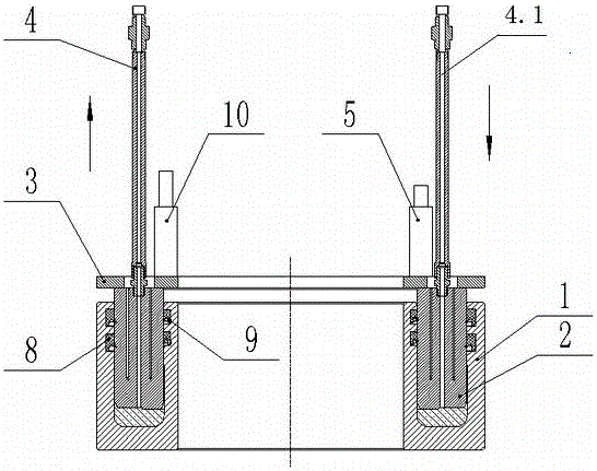
[0025] Attached below figure 1 , 2 3, the device of the present invention is described in detail:

[0026] A self-balancing detection device for foundation piles with internal grouting, which includes an integral annular cylinder 1, an integral annular piston 2, an annular panel 3, an upper displacement pipe 5, a lower displacement pipe 10, a liquid inlet pipe 4.1, a liquid return pipe 4, and a grease nozzle. 6;

[0027] It is characterized in that: the device is installed in the middle section of the foundation pile, the annular panel 3 is welded with the reinforcement cage of the upper section of the foundation pile, the bottom of the annular integral cylinder 1 is welded with the reinforcement cage of the lower section, and the upper displacement tube 5 is welded on the annular panel 3. And through the protective pipe directly to the surface;

[0028] The lower displacement pipe 10 is welded on the end surface of the outer wall of the annular integral cylinder block 1, a...


PUM


Abstract

The invention relates to a foundation pile self-balance detection device with an internal grouting function, in particular to a foundation pile self-balance detection device capable of achieving internal grouting after the bearing capacity of a foundation pile is measured during building foundation pile construction. The foundation pile self-balance detection device comprises an integrally annular cylinder body, an integrally annular piston, an annular panel, an upper shifting pipe, a lower shifting pipe, a liquid inlet pipe, a liquid return pipe and an oil nozzle. The foundation pile self-balance detection device is installed at the middle section of the foundation pile. The annular panel and an upper section reinforcement cage of the foundation pile are welded into a whole, the bottom of the integrally annular cylinder body and a lower section reinforcement cage are welded into a whole, and the upper shifting pipe is welded to the annular panel and directly communicates with the ground surface through a shield pipe. The lower shifting pipe is welded to the end face of the outer wall of the integrally annular cylinder body and directly communicates with the ground surface through a shield pipe. The foundation pile self-balance detection device can detect the pressure difference between the input end and the output end, judges whether the foundation pile operates normally or not, grouting can be carried out through a dual-loop loading pipe after detection is completed, and integration of the foundation pile is ensured.

Description

technical field [0001] The invention relates to a foundation pile self-balance detection device with internal grouting, in particular to a foundation pile self-balance detection device that can be internally grouted after measuring the bearing capacity of the foundation pile in the construction of a building foundation pile. Background technique [0002] The load box used for the bearing capacity test of foundation piles is to place multiple hydraulic cylinders at the bottom of the foundation piles or the middle of the piles to load the foundation piles. In this scheme, the single oil pipe structure is adopted, which cannot accurately judge whether the load box is in normal working condition. Hydraulic oil is used as the loading body. Since the hydraulic oil cannot be integrated with the concrete, it is impossible to carry out secondary grouting inside the device, and there is a potential safety hazard. After the load box is loaded, the pressure cannot be properly relieved,...

Claims


Application Information

Patent Timeline
Patent Type & Authority Applications(China)
IPC IPC(8): E02D33/00
CPCE02D33/00
Inventor 左志群汪涛艾绍文易教良
Owner NANCHANG YONGQI TECH DEV
Why Eureka
Try Eureka