Outdoor weak current equipment box with heat dissipation function

An electrical equipment, outdoor technology, applied in electrical components, substation/switch layout details, substation/switchgear cooling/ventilation and other directions, can solve the problem of insufficient and uneven heat dissipation, affecting the normal operation of electronic components, etc. Sufficient, high heat dissipation efficiency, and the effect of improving heat dissipation efficiency

Pending Publication Date: 2020-05-15
上海威锐电子科技股份有限公司
View PDF0 Cites 5 Cited by
  • Summary
  • Abstract
  • Description
  • Claims
  • Application Information

AI Technical Summary

Problems solved by technology

[0003] Weaknesses There are many electronic components installed in the equipment box. During the working process of the electronic components, a large amount of heat will be emitted, so it needs to be dissipated, otherwise it will affect the normal operation of the electronic components. The existing heat dissipation method is directly through the fixedly installed fan. Heat dissipation, but due to the blocking of the equipment, there is insufficient and uneven heat dissipation

Method used


Image

  • Outdoor weak current equipment box with heat dissipation function
  • Outdoor weak current equipment box with heat dissipation function
  • Outdoor weak current equipment box with heat dissipation function

Examples


Embodiment 1

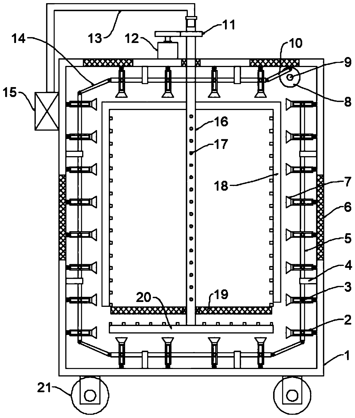
[0024] see Figure 1~2 , in an embodiment of the present invention, an outdoor weak current equipment box with heat dissipation function, including a box body 1, an installation mesh plate 19 for installing electronic components and a heat dissipation unit for cooling electronic components, the bottom of the box body 1 Rollers 21 are evenly and symmetrically fixedly installed, and the rollers 21 are self-locking rollers, which are convenient for the device to move. The box body 1 is equipped with a box door. On the body 1, ventilation nets 6 are installed on the top and side walls of the box body 1, and the heat dissipation unit includes a blowing nozzle 7, a mounting rod 2, a driving rod 5, a first motor 9, a turntable 8, and a first connecting rod 10 and the second connecting rod 14, the inner wall of the box body 1 is hingedly installed with a mounting rod 2 at intervals in the circumferential direction, and the end of the mounting rod 2 away from the inner wall of the box ...

Embodiment 2

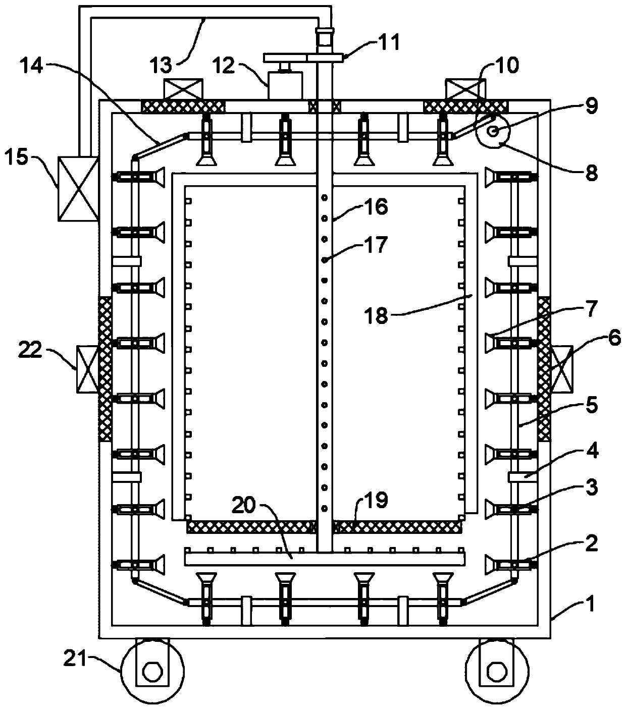
[0027] see image 3 The difference between this embodiment of the present invention and Embodiment 1 is that, further, an exhaust fan 22 is installed on the ventilation net 6 for extracting the hot air in the box body 1 to speed up the circulation of the air.

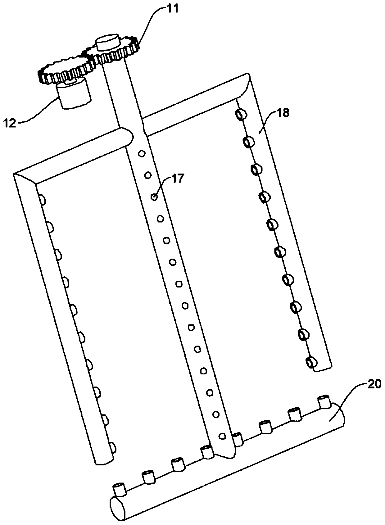
[0028] The working principle of the present invention is: when working, start the first motor 9, the first motor 9 drives the turntable 8 to rotate, the turntable 8 drives the drive rod 5 connected to it to reciprocate through the first connecting rod 10, and the drive rod 5 passes through the second The connecting rod 14 drives the rest of the driving rod 5 to reciprocate, the driving rod 5 drives the installation rod 2 to swing, and the installation rod 2 drives the blowing nozzle 7 to swing, constantly changing the blowing heat dissipation angle, expanding the heat dissipation range and improving the heat dissipation efficiency, and the heat dissipation fan 15 works , the cooling air enters the hollow rotating shaft ...


PUM


Abstract

The invention discloses an outdoor weak current equipment box with a heat dissipation function. The box comprises a case body, a mounting net plate used for mounting an electronic element and a heat dissipation unit used for dissipating heat of the electronic element, the heat dissipation unit comprises a blowing nozzle, a mounting rod, a driving rod, a first motor, a turntable, a first connectingrod and a second connecting rod; the heat dissipation unit further comprises a hollow rotating shaft, a power mechanism used for driving the hollow rotating shaft to rotate, side heat dissipation pipes and a bottom heat dissipation pipe. The heat dissipation unit is arranged, the turntable drives the driving rod connected with the turntable to reciprocate through the first connecting rod, the driving rod drives the other driving rods to reciprocate through the second connecting rod, the driving rod drives the mounting rod to swing, and the mounting rod drives the blowing nozzle to swing, so that the blowing heat dissipation angle is continuously changed, the heat dissipation range is expanded, and the heat dissipation efficiency is improved; the hollow rotating shaft drives the side heatdissipation pipes and the bottom heat dissipation pipe to rotate, the side heat dissipation pipes conduct circumferential air blowing heat dissipation, the bottom heat dissipation pipe forms cyclone in a rotating mode, heat dissipation is sufficient and uniform, and the heat dissipation efficiency is high.

Description

technical field [0001] The invention relates to the technical field of electric equipment, in particular to an outdoor weak current equipment box with heat dissipation function. Background technique [0002] The weak current box, as the name implies, is a centralized box for weaker voltage lines, such as network cables, telephone lines, computer monitors, USB cables, TV VGA, color difference, antennas, etc. can be placed in it; and if these things are not placed in order, it is a Large balls of thread are very messy, appearing disharmonious, and will affect cleaning. In short, the weak current box is used to install these devices and manage the wires. [0003] Weaknesses There are many electronic components installed in the equipment box. During the working process of the electronic components, a large amount of heat will be emitted, so it needs to be dissipated, otherwise it will affect the normal operation of the electronic components. The existing heat dissipation method...

Claims


Application Information

Patent Timeline
Patent Type & Authority Applications(China)
IPC IPC(8): H02B1/56H02B1/46
CPCH02B1/46H02B1/565
Inventor 孟新春
Owner 上海威锐电子科技股份有限公司
Why Eureka
Try Eureka