Radiator with folding fins and preparation method of radiator

A heat sink and fin technology, applied in the field of heat sink with folded fins and its preparation, can solve the problems of poor flatness, poor welding sealing, poor welding stability, etc., to reduce material costs and maintain flatness , the effect of temperature equalization

Pending Publication Date: 2020-05-15
DONGGUAN ZHENGKANG ELECTRONICS
View PDF0 Cites 6 Cited by
  • Summary
  • Abstract
  • Description
  • Claims
  • Application Information

AI Technical Summary

Problems solved by technology

[0005] Existing VC radiators have the following problems: the existing structure requires a large number of copper pillars, and the cost is high; the copper pillars need to be placed manually, the labor cost is high, and the production efficiency is extremely low. In the process of operation and handling, it is easy to cause the copper column to fall, and finally cause poor flatness.
Secondly, the welding sealing is poor, the welding stability is poor, and gaps are prone to appear, resulting in reduced heat dissipation effect

Method used


Image

  • Radiator with folding fins and preparation method of radiator
  • Radiator with folding fins and preparation method of radiator
  • Radiator with folding fins and preparation method of radiator

Examples


Embodiment 1

[0040] see Figure 1-11 As shown, a heat sink with folded fins includes a heat dissipation substrate 1, the heat dissipation substrate 1 is a VC structure, the heat dissipation substrate 1 includes a base and an upper plate, and the connecting edge of the base and the upper plate is welded by diffusion welding or laser welding or solder The base 11 is provided with a concave cavity, and folded fins are arranged in the concave cavity, and a circle of welding surface 112 is arranged outside the cavity, and a circle of solder is placed on the welding surface 112. The upper plate 12 covers the welding surface and closes the opening, and the base 11 and the upper plate 12 are assembled together for solder welding. After the base 11 and the upper plate 12 are heated to a temperature slightly higher than the melting point of the solder, the solder The material melts and is sucked and filled between the welding surface and the upper plate by means of capillary action. The liquid brazi...

Embodiment 2

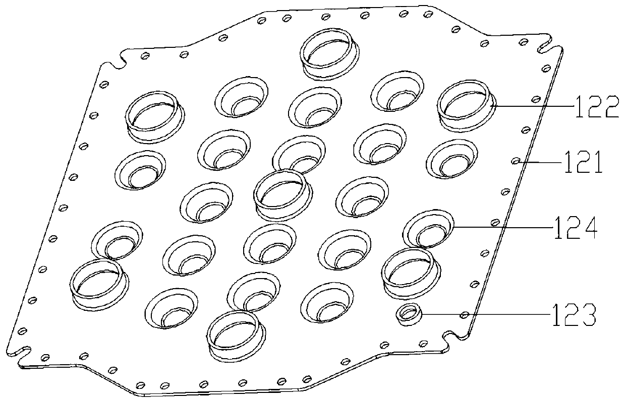
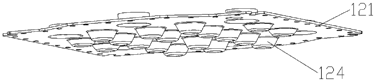
[0047] This embodiment is a modified example of Embodiment 1, and the difference lies in that a circle of solder holes 121 is distributed on the edge of the upper plate 12 corresponding to the position of the welding surface, and the solder holes 121 are used for injecting solder.

[0048] The welding surface is usually distributed with a large number of tiny cavities or cracks (that is, the welding surface is uneven). When the upper plate is pressed against the opening of the base, the upper plate is pressed against the welding surface, which will seriously deform, twist or even break the solder on the welding surface , resulting in uneven and discontinuous structure of the brazing seam and a large void area, which will affect the vacuum degree of the heat dissipation substrate, and may even overflow into the concave cavity of the base. Just like in daily life, two pieces of paper are bonded by glue Put another paper on the glue paper, the glue will be squeezed out of the gap ...

Embodiment 3

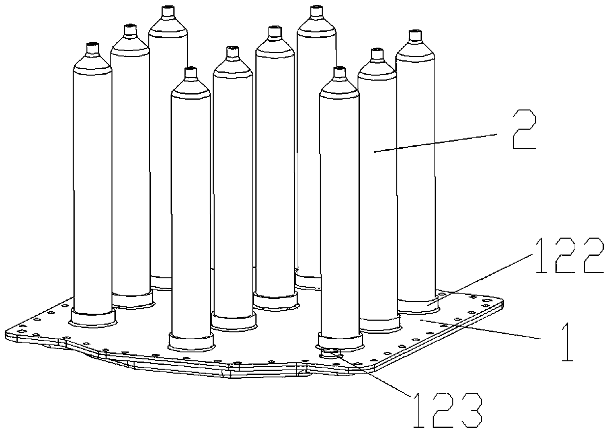
[0051] This embodiment is a modification of Embodiments 1 and 2. The change is that this embodiment is applied to a 3D heat sink, and the heat is conducted upwards through heat pipes to accelerate heat dissipation. Several heat pipes are provided on the heat dissipation substrate. , the heat pipe is provided with a set of fins, the heat pipe is a hollow tube with an opening at one end, the upper surface of the upper plate 12 is provided with a suction pipe 122 corresponding to the heat pipe, and the suction pipe 122 It includes a pre-punched hole and a flange integrated with the pre-punched hole. The flange is protruding relative to the upper surface of the upper plate. The open end of the heat-conducting pipe is inserted into the pumping tube. Through, the outer wall surface of the opening end is connected with the inner wall surface of the flange in a planar manner. Changing the usual "line-to-surface" contact to "surface-to-surface" contact makes up for the shortcomings of ...


PUM


Abstract

The invention relates to a radiator with folding fins. The radiator comprises a radiating substrate, the radiating substrate comprises a base and an upper plate, the base is provided with a concave cavity with an upward opening, the upper plate is used for covering the base and sealing the opening, a vacuum cavity is formed between the upper plate and the base, and the folding fins are arranged inthe vacuum cavity. The folding fins form a plurality of directional airflow channels; the heated airflow flows into the cold area from the hot area according to the directional airflow channels, so agood airflow guide effect is achieved; the problem of airflow turbulence is avoided, the problem that the heat dissipation efficiency is reduced due to airflow turbulence is avoided, the folding finshave good airflow guiding performance and flow towards all the folding cavities under the action of the airflow channels, and therefore airflow can fully circulate and evenly flow in the vacuum cavity and fully exchange heat with air in a cold area. Compared with an existing radiator with a copper column as a supporting structural part, the heat dissipation effect of the radiator is remarkably improved.

Description

technical field [0001] The invention relates to the technical field of radiators, in particular to a radiator with folded fins and a preparation method thereof. Background technique [0002] With the rapid development of electronic equipment, the operating ability of electronic equipment is getting stronger and stronger, and the heat generated by the operation is increasing. The vapor chamber (VC for short) is used as a heat sink in high-power or highly integrated electronic products The device is widely used. When used properly, it can be simply understood as a component with a very high thermal conductivity. The vapor chamber has the following advantages: 1. Low space requirements, 2. Large contact area, 3. Fast thermal response. These features can be applied to heat sinks to reduce thermal spreading resistance and hot spots. [0003] The application of VC is divided into 2D VC radiator and 3D VC radiator. The 2D VC radiator is a plate radiator, which realizes the heat ...

Claims


Application Information

Patent Timeline
Patent Type & Authority Applications(China)
IPC IPC(8): H05K7/20
CPCH05K7/20327H05K7/20336
Inventor 赖耀惠徐海长李龙荣
Owner DONGGUAN ZHENGKANG ELECTRONICS
Why Eureka
Try Eureka