Hot metal ladle

A ladle and iron slag technology, applied in the direction of casting melt containers, metal processing equipment, casting equipment, etc., to achieve the effect of good product quality

Active Publication Date: 2020-05-19
桐乡合德机械有限公司
View PDF14 Cites 1 Cited by
  • Summary
  • Abstract
  • Description
  • Claims
  • Application Information

AI Technical Summary

Problems solved by technology

[0004] The purpose of the present invention is to overcome the shortcomings of the prior art that the iron slag will be poured out, thereby affecting the product quality, and to propose a ladle that does not pour out the iron slag and has good product quality

Method used


Image

  • Hot metal ladle
  • Hot metal ladle
  • Hot metal ladle

Examples


Embodiment

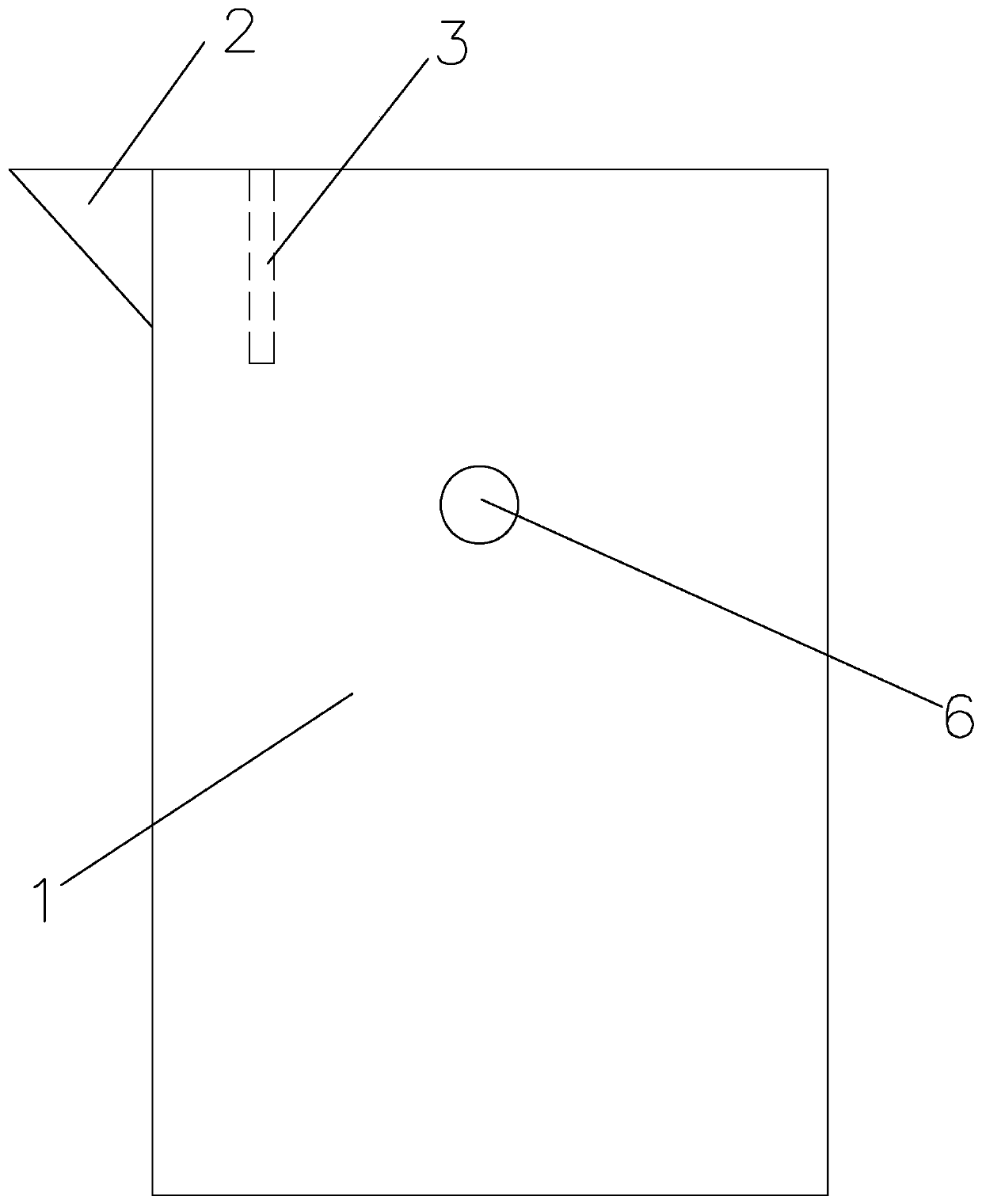
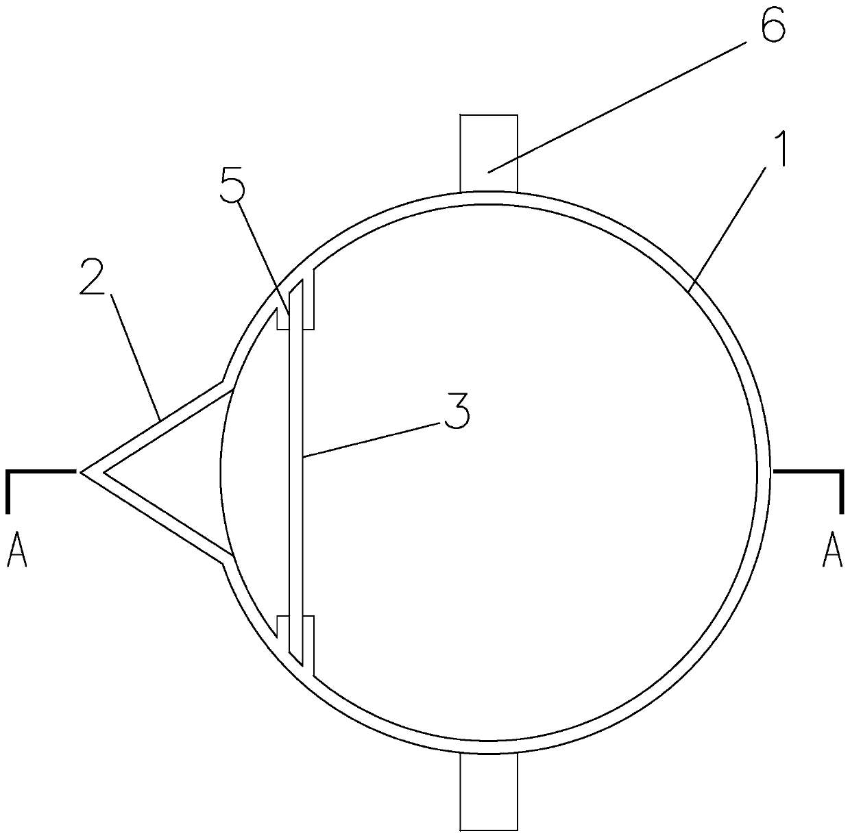
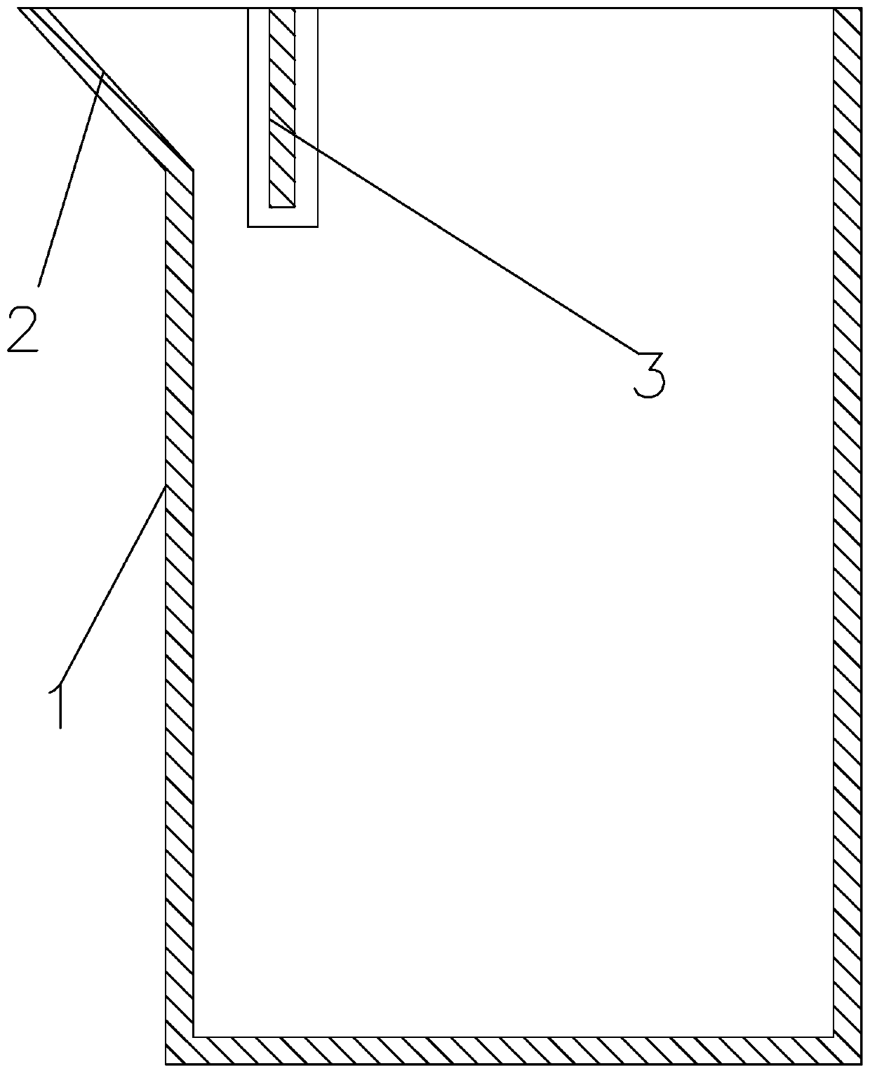
[0025] see Figure 1 to Figure 8 , a ladle, comprising a barrel 1, a mouth 2 located at the mouth of the barrel 1, and a rotating shaft 6 outside the barrel 1, wherein the barrel 1 is provided near the mouth 2 There is a slag retaining plate 3 for blocking iron slag 24 when pouring molten iron 4, the inner side wall of the barrel part 1 is provided with a slot 5 adapted to the slag retaining plate 3 at a position corresponding to the slag retaining plate 3, and the slag retaining plate 3 The edges on opposite sides are located in the slot 5; the height of the bottom of the slag retaining plate 3 is lower than that of the bottom of the mouth 2; a base 8 is provided under the barrel 1, and a bracket 9 is fixedly connected to the base 8 , the barrel part 1 is a cylindrical structure, the outer side of the barrel part 1 is covered with a coaxial rotating ring 7, the rotating ring 7 is connected to the barrel part 1 in rotation, and the outer side of the barrel part 1 is provided o...


PUM


Abstract

The invention discloses a hot metal ladle, and relates to the technical field of casting. The hot metal ladle comprises a barrel part, a nozzle part located at a barrel opening of the barrel part, anda rotating shaft located outside the barrel part, a slag blocking plate used for blocking iron slag during hot metal pouring is arranged at the position, close to the nozzle part, in the barrel part,inserting grooves matched with the slag blocking plate are formed in the position, corresponding to the slag blocking plate, of the inner side wall of the barrel part, and the edges of the two opposite sides of the slag blocking plate are located in the inserting grooves. According to the hot metal ladle, iron slag is not poured out, the product quality is good, the iron slag on the inner wall ofthe barrel part can be brushed off, and the thick iron slag is prevented from being accumulated on the inner side wall of the barrel part.

Description

technical field [0001] The invention belongs to the technical field of casting, in particular to a ladle. Background technique [0002] When pouring molten iron in existing ladles, the iron slag on the upper surface of the molten iron is often poured out together, thereby affecting the quality of the product. [0003] Chinese patent CN108465804A, the patent name is "a molten iron ladle"; it includes a ladle body, a shaft assembly, a support assembly and a cover assembly. The ladle body and adjust the angle of the ladle body through the handle. The supporting components include a hook, a beam and a column. The hook is installed on the beam. There are two columns, which are respectively located on both sides of the ladle body and connected vertically to the two ends of the ladle shaft. The crossbeam is vertically connected between the upright columns, and the cover assembly includes a cover cover, a curved beam, a connecting shaft and a support rod connected in sequence, and ...

Claims


Application Information

Patent Timeline
Patent Type & Authority Applications(China)
IPC IPC(8): B22D41/02B22D41/04B22D41/06B22D41/00
CPCB22D41/001B22D41/02B22D41/04B22D41/06
Inventor 孙袁倪炳华
Owner 桐乡合德机械有限公司
Why Eureka
Try Eureka