
An ultra-precise flexible rotor double-sided on-line deweighting dynamic balancing system

A flexible rotor and balance system technology, applied in metal processing equipment, welding equipment, manufacturing tools, etc., can solve problems affecting production efficiency, high precision, and inability to guarantee, so as to save production consumption costs, improve balance efficiency, and save labor cost effect

Active Publication Date: 2021-02-02
XI AN JIAOTONG UNIV
View PDF9 Cites 0 Cited by
  • Summary
  • Abstract
  • Description
  • Claims
  • Application Information

AI Technical Summary

Problems solved by technology

However, the on-site balance needs to be corrected manually, and a certain number of starts and stops are required during the balance process, which affects production efficiency. In addition, the traditional manual correction method cannot guarantee high accuracy. Mechanical force will be generated on the rotor during weight removal, which may cause adverse effects such as deformation or damage
[0004] With the rapid laser removal technology being more and more widely used, laser processing, as a non-contact processing method, not only does not generate mechanical force when removing materials, but also has high removal accuracy, short laser pulse action time, and can Precisely cut off objects in a rotating state at a specified position, and the high-speed flexible rotor works in a step-over range. In dynamic balancing, ultra-high-precision weight removal is especially needed. Laser weight removal shows great advantages here. However, no relevant literature has been published

Method used


Image

  • An ultra-precise flexible rotor double-sided on-line deweighting dynamic balancing system
  • An ultra-precise flexible rotor double-sided on-line deweighting dynamic balancing system
  • An ultra-precise flexible rotor double-sided on-line deweighting dynamic balancing system

Examples


Embodiment Construction

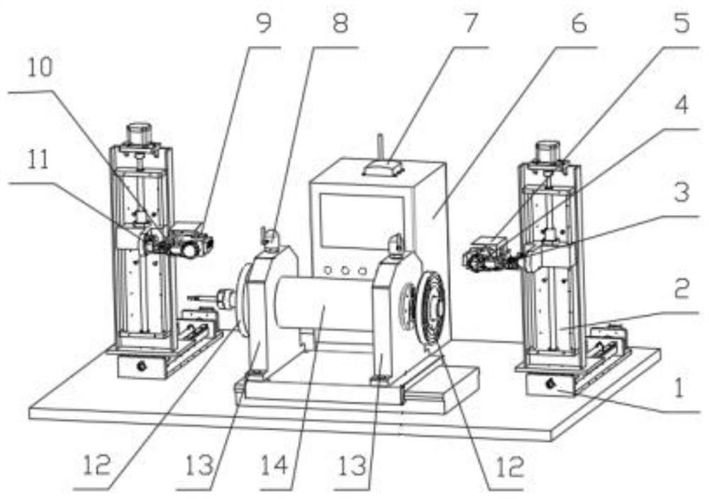
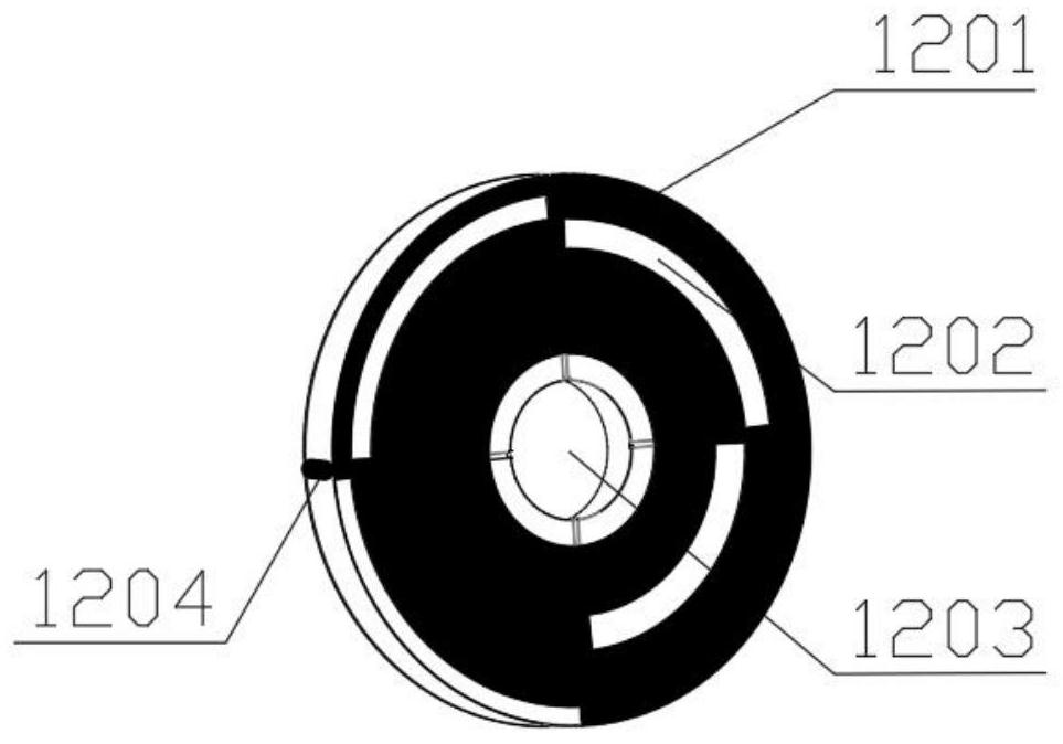
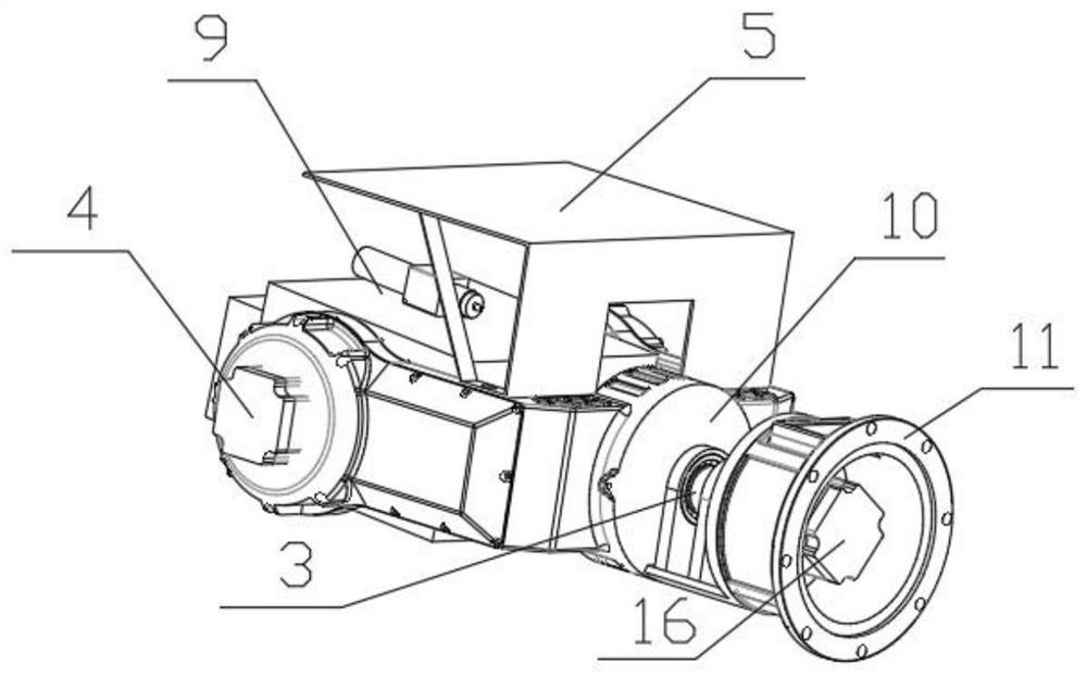
[0020] refer to figure 1 , figure 2 , image 3 and Figure 4 , an ultra-precision flexible rotor double-sided on-line weight-removing dynamic balancing system, including an ultra-high-speed flexible spindle 14, the ultra-high-speed flexible spindle 14 is supported on a spindle fixture 13, and unbalanced weight-removing discs are installed at both ends of the ultra-high-speed flexible spindle 14 12. Under the high-speed rotation of the ultra-high-speed flexible spindle 14, the laser can accurately remove the materials in the different phase de-emphasis areas 1202 of the unbalanced de-weighting disc 12 to realize the quality adjustment of the entire spindle system, and complete the unbalanced quality compensation. Unbalanced de-weighting disc 12 is used as the weight removal object, avoiding the weight removal directly on the ultra-high-speed flexible spindle 14; each unbalanced weight removal disc 12 is equipped with a laser online weight removal system, and two laser online...


PUM


Abstract

The invention discloses a double-sided online de-weighting dynamic balancing system for an ultra-precise flexible rotor. The system comprises an ultra-high-speed flexible main shaft, the ultra-high-speed flexible main shaft is supported on a main shaft clamp, unbalanced de-weighting discs are installed at the two ends of the ultra-high-speed flexible main shaft, and a laser online de-weighting system is arranged beside each unbalanced de-weighting disc in a matched mode. The two laser on-line de-weighting systems are connected with a measurement and control system, and the laser on-line de-weighting systems achieve position adjustment in the up-down direction and the left-right direction and rotary motion posture adjustment of a de-weighting laser in the two directions. The measurement andcontrol system realizes functions of vibration signal acquisition and accurate extraction under complex working conditions, laser de-weight system position and de-weight laser posture adjustment control, laser pulse emission control and man-machine interaction. According to the system, through combining the laser rapid removal technology, the unbalance test and automatic de-weighting functions ofthe ultra-high-speed flexible rotor in a rotating state are realized, the labor cost is saved, and the balance efficiency is greatly improved.

Description

technical field [0001] The invention relates to the technical field of dynamic balancing of high-speed rotors, in particular to an ultra-precise flexible rotor double-sided online weight-removing dynamic balancing system. Background technique [0002] With the advancement and development of science and technology, the degree of automation of mechanical equipment is constantly improving, and the functions are also increasing. At the same time, the structure of mechanical equipment is becoming more and more complex. If a failure occurs, its disassembly and maintenance costs and production will be affected. It has caused great losses to the enterprise, so people hope that the equipment can run stably for a long time and maximize its production capacity; this requires the ability to accurately grasp the operating status of mechanical equipment and timely and efficiently carry out fault suppression. Rotating machinery occupies a large proportion in our current mechanical field. 6...

Claims


Application Information

Patent Timeline
Patent Type & Authority Patents(China)
IPC IPC(8): B23K26/36B23K26/70
CPCB23K26/36B23K26/702
Inventor 运侠伦袁世珏梅雪松姜歌东王晨庞哲凯
Owner XI AN JIAOTONG UNIV
Learn More