Fully-automatic welding device for spiral bin

A fully automatic welding and spiral warehouse technology, applied in other manufacturing equipment/tools, manufacturing tools, etc., can solve the problems of high precision adjustment of workers' technical equipment, heavy welding work, poor sealing, etc., to avoid major safety accidents. Occurrence, time-saving and labor-saving work efficiency, the effect of neat and consistent welding position

Pending Publication Date: 2020-05-19
石家庄诚鼎环保科技有限公司
View PDF0 Cites 0 Cited by
  • Summary
  • Abstract
  • Description
  • Claims
  • Application Information

AI Technical Summary

Problems solved by technology

[0003] 1. German Lipp spiral bite coiling process; its advantages: good overall structure, small amount of materials used, light weight, disadvantages: heavy preparation work, high requirements for the adjustment accuracy of workers' technical equipment, and production materials must be customized. The maintenance cost of the produced silo during operation is extremely high and unaffordable
Disadvantages: ① All components must be strictly and precisely processed in the factory ② During the construction process, if there is any mismatch between components, they must be returned to the factory for reprocessing ③ The overall structure is not good, easy to deform, poor sealing, small pressure, Not suitable for large silos
Disadvantages: the labor intensity of the workers is very high, the production efficiency is low, the calibration workload is large, the welding work is heavy, the manufacturing cost is high, more than 50% of the staff must be professional and experienced technicians, and there are many hidden safety factors in the construction process

Method used


Image

  • Fully-automatic welding device for spiral bin
  • Fully-automatic welding device for spiral bin
  • Fully-automatic welding device for spiral bin

Examples


specific Embodiment approach 1

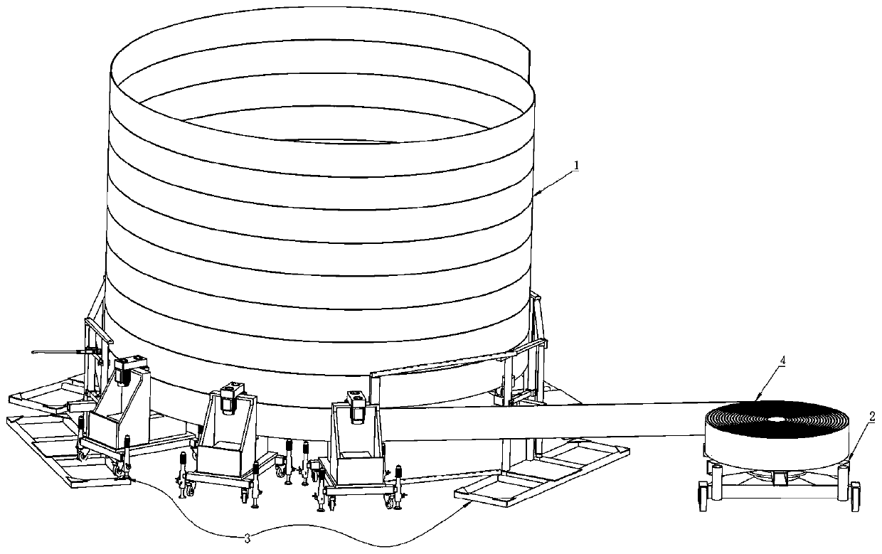
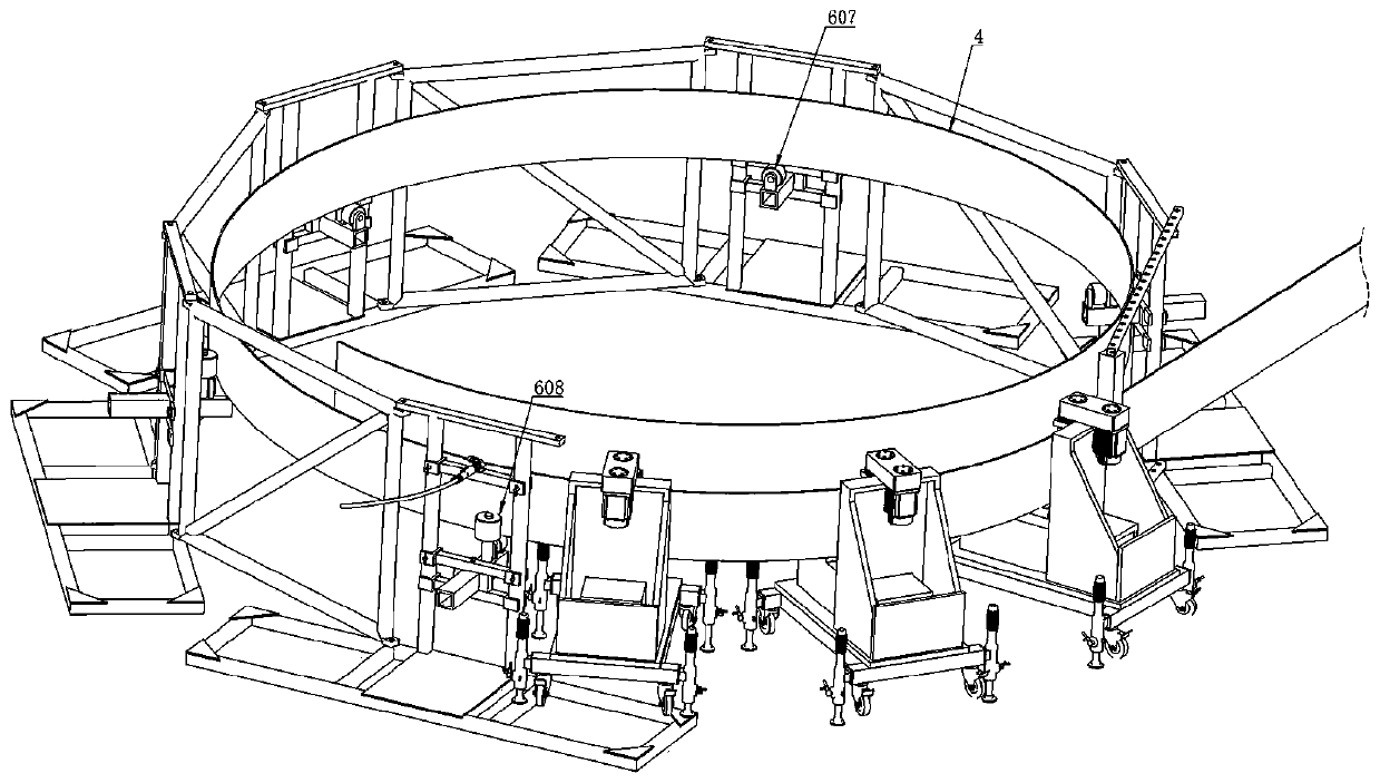
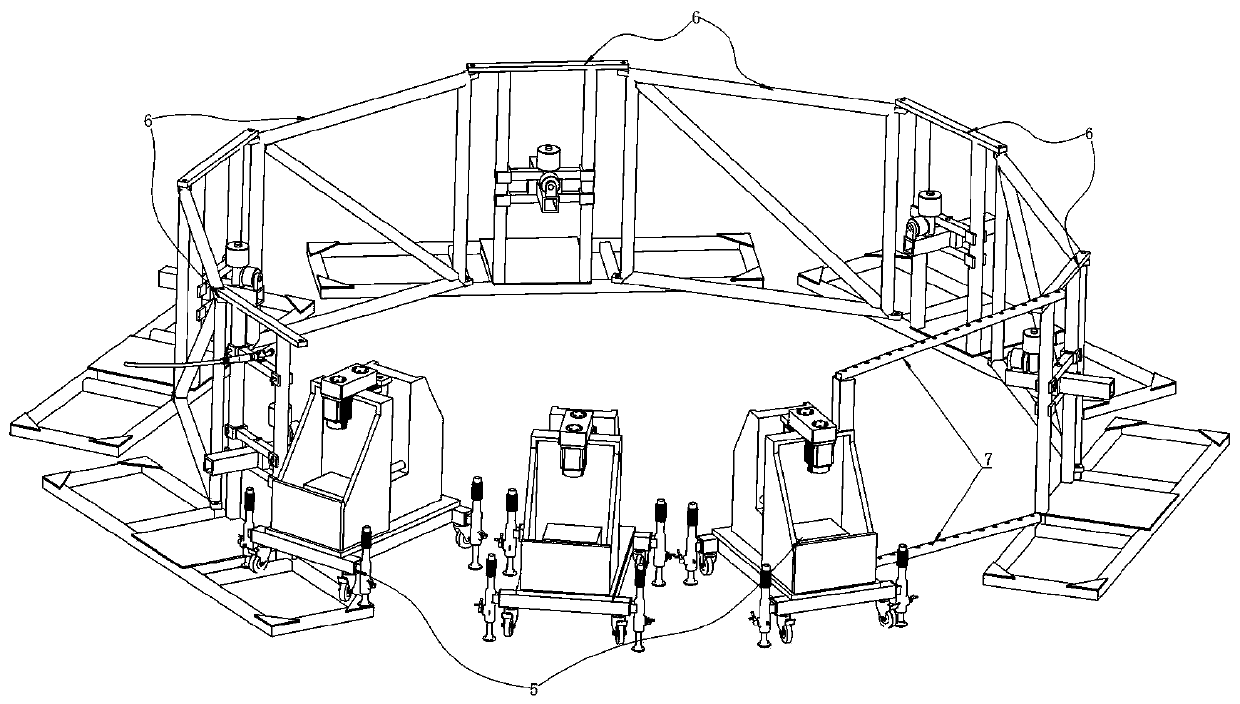
[0034] Specific implementation mode one: combine Figure 1-9 As shown, a fully automatic welding device for a spiral bin is characterized in that it includes a spiral bin 1, an unwinding machine 2 and a vertical lifting automatic welding device 3; One side; the uncoiler 2 is provided with a steel strip 4; the spiral bin 1 is welded by the steel strip 4; the vertical lifting type automatic welding device 3 includes a bending group 5, a bracket group 6 and supplementary The connecting rod 7; the bending group 5 is composed of a plurality of driving bending machines 501; the bracket group 6 is composed of a plurality of fixing frames 601, connecting frames 602 and brackets 603; Wheels 502 and legs 503 are raised.

[0035] Preferably, a gap 504 is provided above the middle of the drive bending machine 501; a gearbox 505 is fixedly installed on the top side of the gap 504 on the drive bender 501; a servo drive is fixedly installed on the input side of the gearbox 505. The motor 5...


PUM


Abstract

The invention relates to the technical field of welding for spiral bins, and especially relates to a fully-automatic welding device for a spiral bin. The fully-automatic welding device for the spiralbin comprises a bending group, a support group and a supplementary connection rod, wherein the bending group is composed of a plurality of drive bending machines, and the support group is composed ofa plurality of fixed frames, a connection frame and a bracket; and the fixed frames and the connection frame are mutually spliced and fixed, the fixed frame at the tail end is connected with the drivebending machine at the head end through the supplementary connection rod to form a whole welding space, steel strips are driven to be subjected to bending conveying through a bending machine during welding, the steel strips are upwards-spiral, the edges of the steel strips are overlaid together, splicing joints are aligned through a fixed welding gun for welding in an upward conveying process forthe steel strips, and then the function of automatically welding the spiral bin is realized. Manual operation is not needed in a whole production process for the spiral bin, so that the time and thelabor are saved, and the working efficiency is greatly increased; and due to a design for the vertically-lifting fully-automatic welding device, bending forming does not need to be carried out on thesteel strips, so that low equipment cost and later-period repair expense, and simple field installation and construction are achieved.

Description

technical field [0001] The invention relates to the technical field of spiral bin welding, in particular to a fully automatic welding device for a spiral bin. Background technique [0002] At present, my country's national defense construction is developing rapidly, and the demand for various large-scale silos, storage tanks, silos and other steel structure equipment is increasing. The requirements for production efficiency and quality are getting higher and higher. Our current common silo production processes are as follows: [0003] 1. German Lipp spiral bite coiling process; its advantages: good overall structure, small amount of materials used, light weight, disadvantages: heavy preparation work, high requirements for the adjustment accuracy of workers' technical equipment, and production materials must be customized. The maintenance costs of the produced silos during operation are extremely high and unaffordable. If it is used to store liquid, the sealing cost is high...

Claims


Application Information

Patent Timeline
Patent Type & Authority Applications(China)
IPC IPC(8): B23P23/00
CPCB23P23/00
Inventor 吴建旺张振贤贾素丽甘玉静吴思佳吴思妍张程烨
Owner 石家庄诚鼎环保科技有限公司
Why Eureka
Try Eureka