
Injection mold for automobile air guide plate

A technology of injection mold and air deflector, which is applied to household appliances, other household appliances, household components, etc., to achieve the effect of improving work efficiency

Pending Publication Date: 2020-05-19
宁海佳运模具有限公司
View PDF0 Cites 0 Cited by
  • Summary
  • Abstract
  • Description
  • Claims
  • Application Information

AI Technical Summary

Problems solved by technology

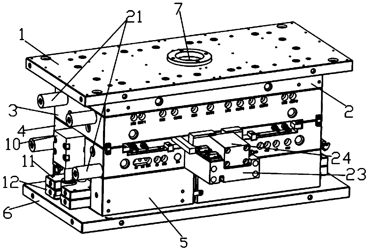
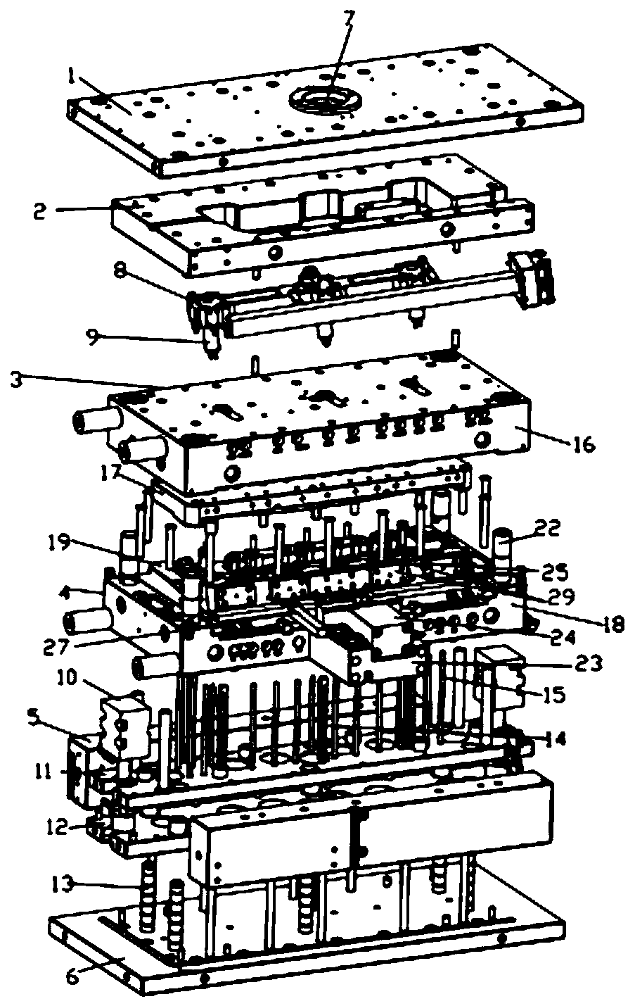
[0005] An injection mold for an automobile wind deflector, comprising a top plate, a hot runner plate, a fixed mold mechanism, a movable mold mechanism, mold feet and a bottom plate, the bottom plate is connected with the movable mold mechanism through the mold feet, and the movable mold mechanism is located on the fixed mold Below the mechanism, the fixed mold mechanism is connected with the top plate through the hot runner plate, and the top plate is provided with a gate, and the gate is connected with a splitter plate, and the splitter plate is fixed in the hot runner plate, and the Two or more hot nozzles are arranged on the manifold, one end of the hot nozzle communicates with the gate, the other end of the hot nozzle communicates with the fixed mold mechanism and the movable mold mechanism, and the movable mold Between the mechanism and the bottom plate, there are an ejector cylinder, an upper ejector plate, a lower ejector plate and a top guide post, one end of the top guide post is fixed on the bottom plate, and the other end of the top guide post penetrates the lower ejector plate and the upper ejector plate, the upper ejector plate and the lower ejector plate are located inside the mold foot, and the upper ejector plate is located above the lower ejector plate, the lower ejector plate is located above the bottom plate, and the bottom plate It is fixedly connected with one end of the ejector cylinder, and the other end of the ejector cylinder is fixed on the left end of the movable mold mechanism, and the movable mold mechanism is located above the upper ejector plate, and the upper ejector plate is provided with a straight ejector block and an ejector pin One end of the thimble and one end of the straight ejector block are fixed on the upper ejector plate, the other end of the ejector pin and the other end of the straight ejector block pass through the movable mold mechanism, and since the gate is connected with a splitter plate, the The manifold is fixed in the hot runner plate, and the manifold is provided with two or more hot nozzles, one end of the hot nozzle is connected to the gate, and the other end of the hot nozzle is connected to the fixed mold mechanism. It is connected with the movable mold mechanism, so that the plastic melt can flow into the splitter plate through the hot runner plate after entering the gate, and then flow in a balanced manner to the fixed mold mechanism and the movable mold mechanism for product molding, thereby improving work efficiency, and at the same time One end of the top guide post is fixed on the bottom plate, and the other end of the top guide post penetrates through the lower ejector plate and the upper ejector plate, the upper ejector plate and the lower ejector plate are located inside the mold foot, and the upper ejector pin The plate is located above the lower ejector plate, the lower ejector plate is located above the bottom plate, the bottom plate is fixedly connected to one end of the ejector cylinder, the other end of the ejector cylinder is fixed to the left end of the movable mold mechanism, and the movable mold mechanism The mold mechanism is located above the upper ejector plate, and the upper ejector plate is provided with a straight ejector block and an ejector pin, one end of the ejector pin and one end of the straight ejector block are fixed on the upper ejector plate, and the other end of the ejector pin is connected to the ejector pin. The other end of the straight ejector block runs through the movable mold mechanism, so that after the product is formed, the ejector cylinder drives the lower ejector plate and the upper ejector plate to move upward along the ejector guide column, and at the same time, the straight ejector block and ejector pin on the upper ejector plate The product is ejected, thereby solving the problem that the ejection mechanism of the traditional automobile wind deflector injection mold in the prior art adopts the inclined top method to cause the automobile wind deflector to be deformed during the whole inclined lifting process of the automobile wind deflector, so it needs to be operated Personnel assist to pry off the car wind deflector in the injection mold, which leads to the problem of low work efficiency, so the specific feature of improving work efficiency

Method used


Image

  • Injection mold for automobile air guide plate
  • Injection mold for automobile air guide plate
  • Injection mold for automobile air guide plate

Examples


Embodiment Construction

[0022] The specific implementation manners of the present invention will be further described below in conjunction with the accompanying drawings, so as to make the technical solution of the present invention easier to understand and grasp.

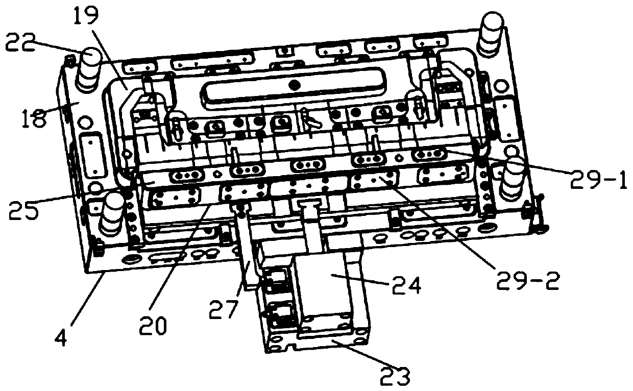
[0023] Such as Figure 1 to Figure 5 As shown, an injection mold for an automobile wind deflector includes a top plate 1, a hot runner plate 2, a fixed mold mechanism 3, a movable mold mechanism 4, a mold foot 5 and a bottom plate 6, and the bottom plate 6 is connected to the movable mold mechanism through the mold foot 5. 4, the movable mold mechanism 4 is located below the fixed mold mechanism 3, the fixed mold mechanism 3 is connected with the top plate 1 through the hot runner plate 2, the top plate 1 is provided with a gate 7, and the gate 7 A diverter plate 8 is connected, and the diverter plate 8 is fixed in the hot runner plate 2, and two or more hot nozzles 9 are arranged on the diverter plate 8, and one end of the nozzle 9 is co...


PUM


Abstract

The invention belongs to the technical field of injection molds and more particularly discloses an injection mold for an automobile air guide plate. The injection mold comprises a top plate, a heat runner plate, a fixed die mechanism, a movable die mechanism, a die foot and a bottom plate. A sprue is arranged on the top plate and is connected with a diversion plate. The diversion plate is fixed inthe hot runner plate, and two or more hot nozzles are arranged on the diversion plate. An ejection oil cylinder, an upper ejection pin plate, a lower ejection pin plate and ejection guide pillars arearranged between the movable die mechanism and the bottom plate. A straight ejection block and an ejection pin are arranged on the upper ejection pin plate. By means of the injection mold for the automobile air guide plate, after plastic melt enters the mold from the sprue and flows to the diversion plate through the hot runner plate, the plastic melt flows into the fixed die mechanism and the movable die mechanism in a balance manner for product forming, and therefore the work efficiency is improved; and meanwhile, after product forming is conducted, the lower ejection pin plate and the upper ejection pin plate are driven by the ejection oil cylinder to move upwards along the ejection guide pillars, the straight ejection block and the ejection pin on the upper ejection pin plate eject aproduct, and therefore the characteristic that the work efficiency is improved is achieved.

Description

technical field [0001] The invention discloses the technical field of injection molds, and more specifically discloses an injection mold for an automobile wind deflector. Background technique [0002] At present, with the development of the automobile industry, during the driving process of the vehicle, the automobile air deflector can gather the air to the maximum extent, so that the air can quickly take away the heat through the condensing device to reduce the temperature of the working parts of the vehicle, and at the same time avoid the airflow disorder inside the cabin With the diversification of automobiles, the driving conditions of automobiles are becoming more and more complicated. What's more, some off-road models may often drive in harsh working conditions such as mud, gravel, and high slopes. Therefore, the wind deflectors of automobiles will There are reinforcing ribs, the purpose of which is to increase the hardness of the automobile wind deflector. However, du...

Claims


Application Information

Patent Timeline
Patent Type & Authority Applications(China)
IPC IPC(8): B29C45/26B29C45/27B29C45/33B29C45/44B29L31/30B29L31/18
CPCB29C45/26B29C45/27B29C45/33B29C45/332B29C45/44B29L2031/18B29L2031/30
Inventor 叶显多
Owner 宁海佳运模具有限公司
Learn More