Photoresist stripping liquid waste liquid recovery system
A technology of waste liquid recovery and stripping liquid, applied in water/sludge/sewage treatment, water pollutants, heating water/sewage treatment, etc. The effect of reducing energy loss, accelerating heat dissipation, and increasing processing efficiency
- Summary
- Abstract
- Description
- Claims
- Application Information
AI Technical Summary
Problems solved by technology
Method used
Image


Examples
Example Embodiment
[0020] Example 1
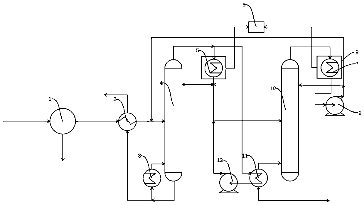
[0021] Such as figure 1 As shown, a photoresist stripping liquid waste recovery system includes a reactor 1, a preheater 2, a first reboiler 3, a normal pressure, negative pressure distillation tower 4, a first condenser 5, and a second The condenser 7, the second pump body 9, the pressurized rectification tower 10, the second reboiler 11 and the first pump body 12, the overall rectification process in the present invention is like the invention with patent number CN105523598B. To repeat, the first condenser 5 and the second condenser 7 are both provided with a heat recovery cover 8. The heat recovery cover 8 is connected to the heat recovery device 6 through a heat transfer tube. The heat recovery cover 8 is used to collect the heat emitted by the condenser. Heat, and at the same time transfer the heat through the heat transfer tube to the heat recovery device 6 for storage and use;
[0022] The heat recovery cover 8 includes an outer shell, an insulating laye...
Example Embodiment
[0027] Example 2
[0028] Such as figure 1 As shown, a photoresist stripping liquid waste recovery system includes a reactor 1, a preheater 2, a first reboiler 3, a normal pressure, negative pressure distillation tower 4, a first condenser 5, and a second The condenser 7, the second pump body 9, the pressurized rectification tower 10, the second reboiler 11 and the first pump body 12, the first condenser 5 and the second condenser 7 are all provided with a heat recovery cover 8, The heat recovery cover 8 is connected to the heat recovery device 6 through a heat transfer tube;
[0029] The heat recovery cover 8 includes an outer shell, an insulating layer laid on the inner wall of the outer shell, and several heat collecting plates laid on the inner wall of the outer shell. The outer shell is arranged outside the first condenser 5 and the second condenser 7, and the heat collecting plate The heat emitted by the condenser can be collected, and the heat collecting plate can heat the...
Example Embodiment
[0034] Example 3
[0035] Such as figure 1 As shown, a photoresist stripping liquid waste recovery system includes a reactor 1, a preheater 2, a first reboiler 3, a normal pressure, negative pressure distillation tower 4, a first condenser 5, and a second The condenser 7, the second pump body 9, the pressurized rectification tower 10, the second reboiler 11 and the first pump body 12, the first condenser 5 and the second condenser 7 are all provided with a heat recovery cover 8, The heat recovery cover 8 is connected to the heat recovery device 6 through a heat transfer tube;
[0036] The heat recovery cover 8 includes an outer shell, an insulating layer laid on the inner wall of the outer shell, and several heat collecting plates laid on the inner wall of the outer shell. The outer shell is arranged outside the first condenser 5 and the second condenser 7, and the heat collecting plate The heat emitted by the condenser can be collected, and the heat collecting plate can heat the...
PUM
 Abstract
Description
Claims
Application Information
 - R&D Engineer
- R&D Manager
- IP Professional
- Industry Leading Data Capabilities
- Powerful AI technology
- Patent DNA Extraction
Browse by: Latest US Patents, China's latest patents, Technical Efficacy Thesaurus, Application Domain, Technology Topic.
© 2024 PatSnap. All rights reserved.Legal|Privacy policy|Modern Slavery Act Transparency Statement|Sitemap