
Blast furnace charging bucket material receiving and distribution device

A material distributing device and material tank technology, applied in the direction of bell and funnel arrangement, etc., can solve the problems of increased maintenance costs and equipment accident risks, wear of the center column body and liner, wear of the center column body of the vertical material tank, etc., to meet the requirements Long-term operation requirements, solve the effect of fast wear and less types of wearing parts

Pending Publication Date: 2020-05-19
LAIWU IRON & STEEL GRP
View PDF0 Cites 0 Cited by
  • Summary
  • Abstract
  • Description
  • Claims
  • Application Information

AI Technical Summary

Problems solved by technology

During the periodic filling process of the traditional material tank, the traditional connecting and distributing trays are repeatedly washed by various raw materials. After 2-3 months of use, there will be wear, wear-through, and uneven distribution of materials, resulting in the center of the vertical material tank. The main body of the column is worn out, and the liner of the tank is worn through at fixed points. If you continue to use it, it will accelerate the wear of the main body of the center column and the liner, which will increase the maintenance cost and the risk of equipment accidents.
At present, with the improvement of equipment, maintenance and operation level, the regular maintenance period of large blast furnaces has gradually been extended from 3 months to more than 5 months, and the service life of traditional receiving and distributing trays of 2-3 months can no longer meet the long-term production Therefore, there is an urgent need for an impact-resistant, wear-resistant and durable device that distributes materials evenly and distributes materials

Method used


Image

  • Blast furnace charging bucket material receiving and distribution device
  • Blast furnace charging bucket material receiving and distribution device
  • Blast furnace charging bucket material receiving and distribution device

Examples


Embodiment Construction

[0019] The present invention is described in further detail now in conjunction with accompanying drawing.

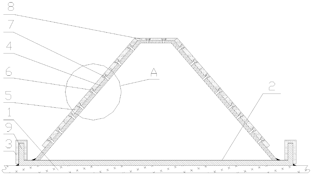
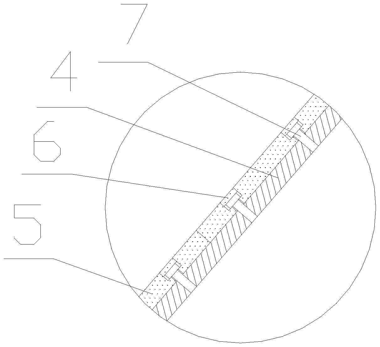
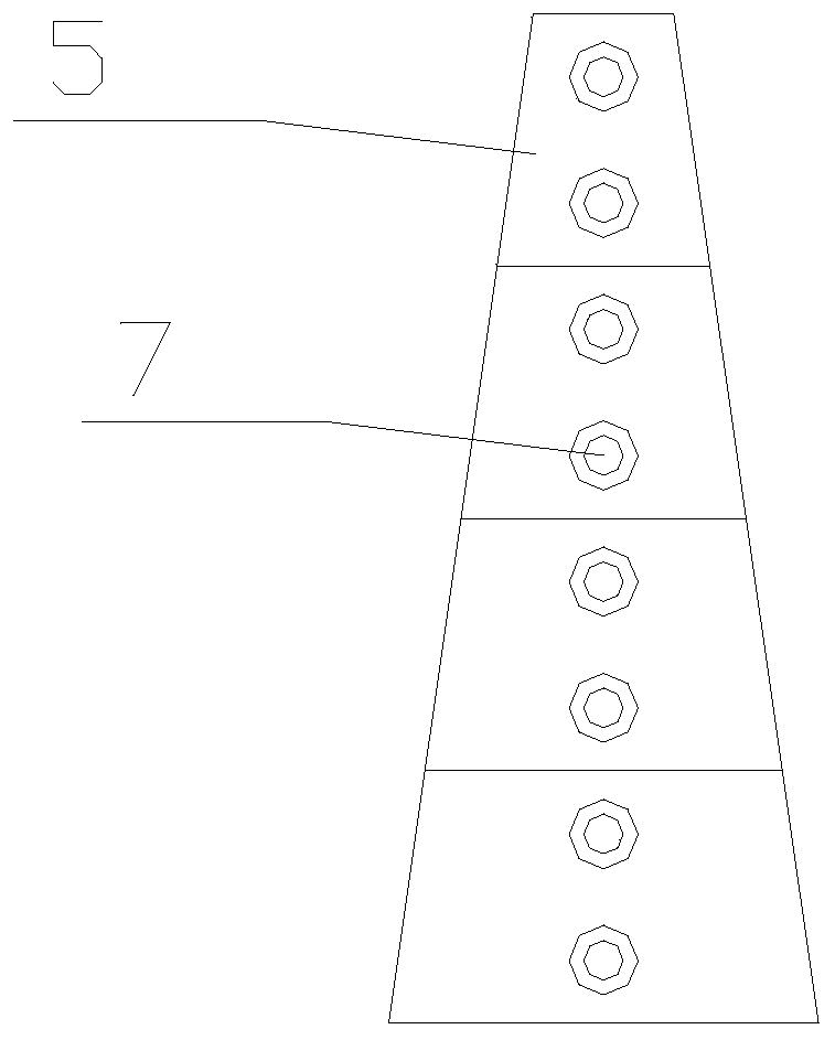
[0020] like figure 1 , 2 As shown, a blast furnace charging tank connecting and distributing device includes a charging tank center column 1, a chassis 2, a chassis ceramic liner 3, and a front prism 4, and the chassis 2 is welded on the charging tank center column 1, and the chassis 2 and The central column 1 of the material tank is concentrically fixed. The bottom of the prism 4 is fixed in the chassis 2, and the outer periphery of the chassis 2 is provided with an integrally formed baffle 9, the chassis 2 and the baffle 9 are integrally formed, and the prism 4 and the chassis 2 are integrally cast, or they can be cast separately It is connected by stainless steel wear-resistant electrode welding, the inner wire bolt hole is processed, and the surface is polished at high points. Chassis 2, front edge platform 4, and fastening bolt 7 are all made of 1Cr18Ni9Ti stainl...


PUM


Abstract

The invention relates to a blast furnace charging bucket material receiving and distribution device. The blast furnace charging bucket material receiving and distribution device comprises a charging bucket center vertical column, a base plate, a base plate ceramic liner plate and a frustum of a regular pyramid; the base plate is fixed to the charging bucket center vertical column; the bottom of the frustum of the regular pyramid is fixed into the base plate, and the periphery of the base plate is provided with a baffle; the base plate ceramic liner plate is fixed to the baffle, and a groove isformed between the baffle and the frustum of the regular pyramid; frustum of the regular pyramid is in a big end down shape, the top surface of the frustum of the regular pyramid is provided with a polygonal ceramic liner plate adapting to the top surface of the frustum of the regular pyramid; the side surfaces of the frustum of the regular pyramid are provided with trapezoidal ceramic liner plates; and the trapezoidal ceramic liner plates and the polygonal ceramic liner plate are fixed to the frustum of the regular pyramid through a plurality of fastening bolts, and a ceramic buckle is fixedto the top of each fastening bolt. The blast furnace charging bucket material receiving and distribution device has the advantages of being resistant to impact during material receiving, good in buffering effect, high in abrasion resistance, uniform in material distribution, small in vulnerable part type during repairing, easy and fast to maintain and the like, the defects that a charging bucketlinear plate is fast in abrasion, short in service life and the like due to the fact that an original structure is uneven in material distribution are effectively overcome, and the blast furnace long-time operation requirement is met.

Description

technical field [0001] The invention relates to the technical field of material transmission components in blast furnace charging tanks, in particular to a blast furnace charging tank connecting and distributing device. Background technique [0002] The modern large blast furnace is mainly based on the bellless furnace top, and its material tanks are mostly string tanks. The material tank is divided into a receiving tank and a weighing tank, which play the role of receiving external raw materials, temporarily storing and weighing materials in the blast furnace production process. During the periodic filling process of the traditional material tank, the traditional connecting and distributing trays are repeatedly washed by various raw materials. After 2-3 months of use, there will be wear, wear-through, and uneven distribution of materials, resulting in the center of the vertical material tank. The main body of the column is worn, the liner of the tank is worn through at fix...

Claims


Application Information

Patent Timeline
Patent Type & Authority Applications(China)
IPC IPC(8): C21B7/20
CPCC21B7/20
Inventor 卜祥伦
Owner LAIWU IRON & STEEL GRP
Learn More