Experiment research system for electrolytic copper foil and using method thereof

An electrolytic copper foil, experimental research technology, applied in the electrolytic process, electrolytic components, electroforming, etc., can solve the problems of loose electrolytic copper foil deposition structure, inability to maintain stable electrolyte composition, cathode concentration polarization, etc., to achieve Reduce the cost of new product development and production, meet the actual production auxiliary requirements, and eliminate the effect of concentration polarization

Active Publication Date: 2020-05-19
JIANGXI UNIV OF SCI & TECH
View PDF5 Cites 4 Cited by
  • Summary
  • Abstract
  • Description
  • Claims
  • Application Information

AI Technical Summary

Problems solved by technology

As far as static electroplating is concerned, the concentration polarization of the cathode is serious, which is likely to cause loose electrolytic copper foil deposition structure, especially high-current deposition is more likely to produce copper powder; at the same time, the electrolyte of electrolytic copper foil is continuously diluted with the electroplating time. Static electroplating cannot maintain the stability of the electrolyte composition; moreover, the electrolytic copper foil is produced stably within the set temperature range, and the constant temperature needs to be considered during the test
Therefore, the current test equipment alone cannot fully meet the needs of actual production. It is urgent to design an electrolytic cell device that can not only eliminate the concentration polarization problem, but also supplement the electrolyte components and keep the temperature constant.

Method used


Image

  • Experiment research system for electrolytic copper foil and using method thereof
  • Experiment research system for electrolytic copper foil and using method thereof
  • Experiment research system for electrolytic copper foil and using method thereof

Examples


Embodiment

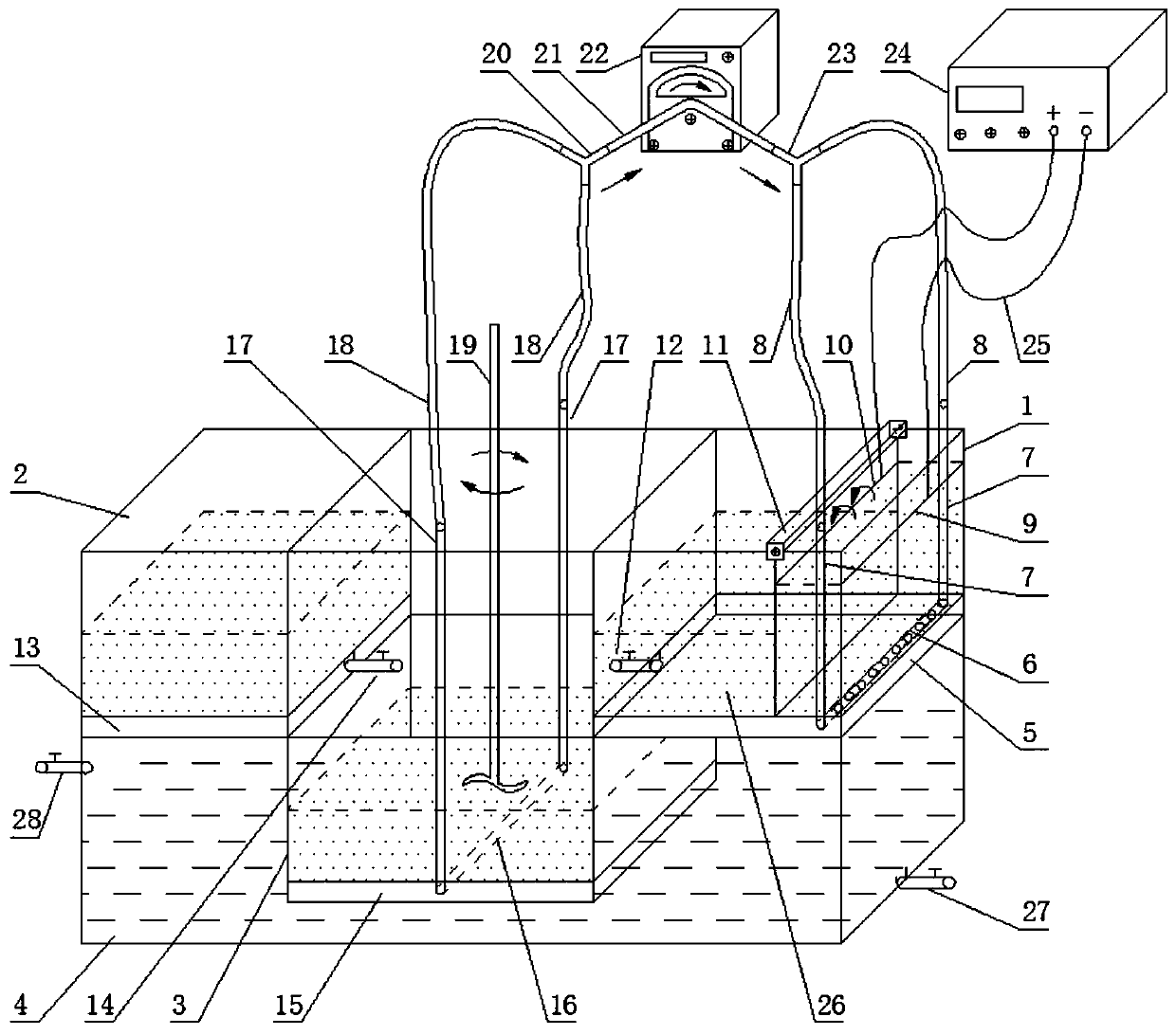
[0038] Such as figure 1 A system for electrolytic copper foil experimental research shown includes an electrolytic cell 1 and a constant current rectifier 24. The electrolytic cell 1 is provided with a vertical cathode plate 9 and an anode plate 10 arranged side by side. The cathode plate 9 It is a pure titanium plate, the anode plate 10 is an iridium-coated titanium plate, and the cathode plate 9 and the anode plate 10 are electrically connected to the positive pole and the negative pole of the constant current rectifier 24 respectively;

[0039]The width of the cathode plate 9 and the anode plate 10 is consistent with the internal width of the electrolytic cell 1, and the bottoms of the negative plate 9 and the anode plate 10 all extend to the bottom of the electrolytic cell 1, and the negative plate 9 is attached to the electrolytic cell 1 The side wall of one side of the electrolytic cell 1 corresponding to the cathode plate 9 is provided with a liquid inlet straight pipe ...


PUM


Abstract

The invention discloses an experiment research system for an electrolytic copper foil and a using method thereof, and belongs to the technical field of electrolytic copper foil experiment. The systemcomprises an electrolytic cell, a constant-current rectifier, a solution supplementing slot, a solution mixing slot, a heating slot, a cathode plate and an anode plate, wherein the upper edge of the electrolytic cell is slidably connected to an anode slide block for mounting the anode plate; an overflow hole is formed in the anode plate; the solution mixing slot and the solution supplementing slotare formed in one side of the electrolytic cell; solution discharge valves are arranged on the bottom of the electrolytic cell and the bottom of the solution supplementing slot; the solution mixing slot communicates with the electrolytic cell through a pipeline; and one heating slot is co-formed below the electrolytic cell and the solution supplementing slot. The using method comprises electrolytic solution preparation, temperature control, parameter setting, copper consumption calculating, electrolytic solution supplementing, copper foil sample obtaining and the like. The experiment researchsystem can eliminate the concentration polarization problem, supplements electrolytic solution components, keeps temperature constant, meets practical production auxiliary requirements, can simplifytest operations, quickens test development efficiency, and reduces new product development and production cost.

Description

technical field [0001] The invention relates to the technical field of electrolytic copper foil experiments, in particular to a system for experimental research on electrolytic copper foils and a method for using the same. Background technique [0002] Electrolytic copper foil is an important conductor raw material for the manufacture of copper clad laminates (CCL), printed circuit boards (PCB), flexible circuit boards (FPC) and lithium-ion batteries (LIB), and is widely used in electronics, communications, computers and other fields. With the rapid development of electronic technology, the market demand for high-performance electrolytic copper foil is increasing. In the production process of electrolytic copper foil, the solution and electrolytic process parameters play a very important role. However, in actual production, due to various conditions, the required electrolytic copper foil cannot be prepared truthfully. Therefore, in order to avoid the trial production process...

Claims


Application Information

Patent Timeline
Patent Type & Authority Applications(China)
IPC IPC(8): C25D1/04C25D17/00C25D21/02C25D21/14C25D21/10
CPCC25D1/04C25D17/00C25D21/02C25D21/10C25D21/14
Inventor 唐云志樊小伟刘耀师慧娟谭育慧张钰松
Owner JIANGXI UNIV OF SCI & TECH
Why Eureka
Try Eureka