Cable bollard for anti-shock protection of pier
An anti-shock and cable pile technology, applied in the field of cable piles, can solve problems such as unfavorable escape, damage to ships and docks, etc.
- Summary
- Abstract
- Description
- Claims
- Application Information
AI Technical Summary
Problems solved by technology
Method used
Image

Examples
specific Embodiment approach 1
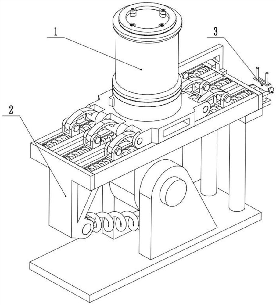
[0028] Combine below figure 1 , figure 2 , image 3 , Figure 4 , Figure 5 , Figure 6 , Figure 7 , Figure 8 , Figure 9 , Figure 10 , Figure 11 This embodiment is described. The present invention relates to a sampling device, more specifically, a bollard for impact protection of a pier, including a bollard 1, a base 2, and a cable puller 3. The device can perform low-impact buffering through a spring. For protection, the device can provide a medium degree of buffer protection through the thrust spring. The device can resist large impacts by breaking away from the bollard, thereby protecting the ship and the wharf. The device can tighten the pulling cable thrown by the ship and bring the main cable over.
[0029] The bollard 1 is located on the top of the base 3 , the bollard 1 is slidingly fitted with the base 3 , and the cable puller 2 is fixed at the rear of the bollard 1 .
specific Embodiment approach 2
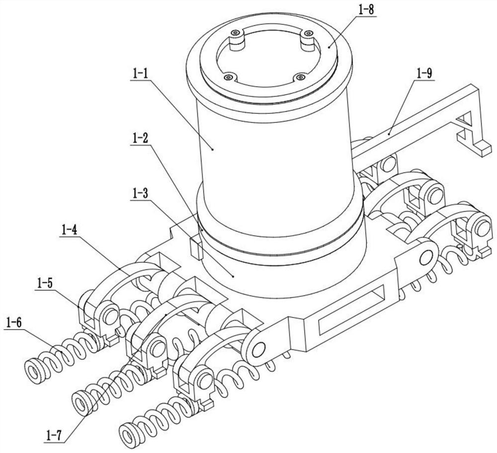
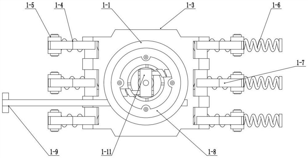
[0031] Combine below figure 1 , figure 2 , image 3 , Figure 4 , Figure 5 , Figure 6 , Figure 7 , Figure 8 , Figure 9, Figure 10 , Figure 11 This embodiment will be described. This embodiment will further describe the first embodiment. The bollard 1 includes a rotating bollard 1-1, a fixed inner pile 1-2, a sliding seat 1-3, a side support piece 1-4, a top Block 1-5, spring 1-6, middle support piece 1-7, fixed ring 1-8, rack one 1-9, friction ring 1-10, connecting sleeve 1-11, bayonet pin 1-12, inner Pile sliding sleeve 1-13, inner spring 1-14, upper toothed plate 1-15, lower tooth column 1-16, gear 1-17, rotating column 1-18, rotating bollard 1-1 is a hollow cylinder, rotating The section of the cable pile 1-1 is I-shaped, the rotating cable pile 1-1 is set on the fixed inner pile 1-2, the fixed inner pile 1-2 is cylindrical, and the lower part of the fixed inner pile 1-2 is in phase with the sliding seat 1-3. Contact, the upper part of the fixed inner pil...
specific Embodiment approach 3
[0033] Combine below figure 1 , figure 2 , image 3 , Figure 4 , Figure 5 , Figure 6 , Figure 7 , Figure 8 , Figure 9 , Figure 10 , Figure 11 Describe this embodiment, this embodiment will further explain the first embodiment, the cable puller 2 includes a tank body 2-1, a hanging post 2-2, a hand wheel 2-3, a top post 2-4, and a rack wheel One 2-5, rack two 2-6, rack wheel two 2-7, motor 2-8, hanging column block 2-9, two-way screw 2-10, the tank body 2-1 is a cuboid, and the tank body 2- 1 There is a chute inside, the upper part of the groove body 2-1 is processed with a long opening, there are two hanging posts 2-2, the lower part of the hanging post 2-2 is fixed on the hanging post block 2-9, and the hand wheel 2-3 It is fixed on one end of the two-way screw 2-10, the top column 2-4 is fixed on the lower part of the tank body 2-1, the top column 2-4 is slidingly matched with the base 3, and the rack wheel 1 2-5 is fixed on the top column 2-4 On, the rac...
PUM
 Abstract
Description
Claims
Application Information
 - R&D
- Intellectual Property
- Life Sciences
- Materials
- Tech Scout
- Unparalleled Data Quality
- Higher Quality Content
- 60% Fewer Hallucinations
Browse by: Latest US Patents, China's latest patents, Technical Efficacy Thesaurus, Application Domain, Technology Topic, Popular Technical Reports.
© 2025 PatSnap. All rights reserved.Legal|Privacy policy|Modern Slavery Act Transparency Statement|Sitemap|About US| Contact US: help@patsnap.com