
Tri-proof lamp facilitating aloft work

A high-altitude operation and three-proof lamp technology, which is applied to the damage prevention measures of lighting devices, air-proof/waterproof devices, and parts of lighting devices. And other issues

Pending Publication Date: 2020-05-19
SHENZHEN HUIKEMEI TECH CO LTD
View PDF0 Cites 0 Cited by
  • Summary
  • Abstract
  • Description
  • Claims
  • Application Information

AI Technical Summary

Problems solved by technology

[0002] Tri-proof lights are usually installed at high altitudes, and the plug housing of the tri-proof lamp is usually fixed in advance with a wire slot plate and a fixed power terminal. When it is damaged, the plug housing, the connected wire slot board and the power terminal need to be replaced as a whole. , which will not be conducive to repair and replacement when damaged, especially when working at high altitudes, which will greatly increase the maintenance cost
For conventional tri-proof lights, the connection method between the plug top cover and the plug shell is as follows: the plug shell is provided with two buckle parts, and the two buckle parts are matched with two buckle grooves on the plug top cover. Buckle or separate, after the top cover of the plug is opened, the top cover of the plug is completely separated from the casing of the plug, especially when working at heights, if the top cover of the plug is not properly placed and removed, it may cause damage to the top cover of the plug falling to the ground and personnel at height Need to pick up

Method used


Image

  • Tri-proof lamp facilitating aloft work
  • Tri-proof lamp facilitating aloft work
  • Tri-proof lamp facilitating aloft work

Examples


Embodiment Construction

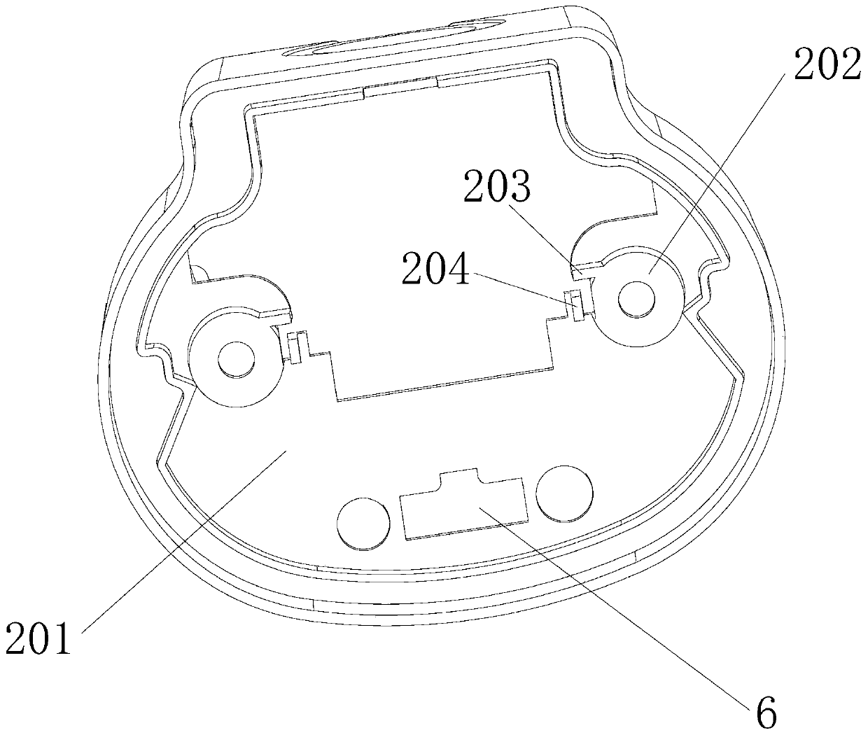
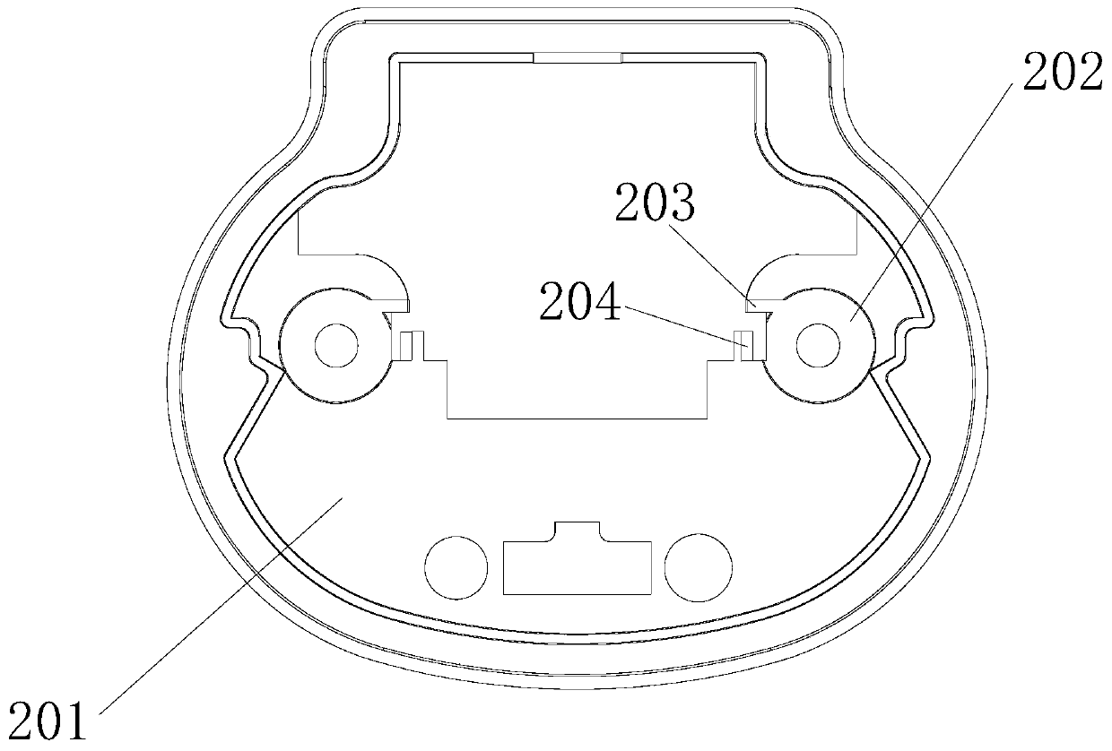
[0031] The present invention will now be further explained in conjunction with the drawings. These drawings are simplified schematic diagrams only to illustrate the basic structure of the present invention in a schematic manner, so they only show the configuration related to the present invention.

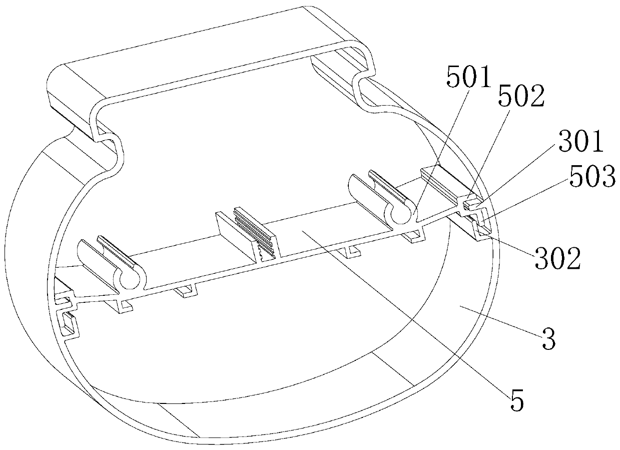
[0032] Such as figure 1 As shown, a tri-proof lamp that is convenient for high-altitude operations has a tube housing 3, the tri-proof lamp further has a push-pull groove plate 5, and the edge of the push-pull groove plate 5 is symmetrically provided with first push-pull grooves, The first push-pull groove is enclosed by a first horizontal guide rail 502 and a first L-shaped guide rail 503, the first push-pull groove is a horizontal guide groove; the tube wall of the lamp housing 3 is symmetrically provided with a second push-pull groove , The second push-pull groove is enclosed by a second horizontal guide rail 301 and a second L-shaped guide rail 302, the second push-pull groove is ...


PUM


Abstract

The invention relates to a tri-proof lamp facilitating aloft work, which is provided with a lamp tube shell and a lower push-pull trough plate, the edge of the lower push-pull trough plate is symmetrically provided with a first push-pull trough, the first push-pull trough is defined by a first transverse guide rail and a first L-shaped guide rail, and the first push-pull trough is a transverse guide groove; second push-pull grooves are symmetrically formed in the tube wall of the lamp tube shell, each second push-pull groove is defined by a second transverse guide rail and a second L-shaped guide rail, and the second push-pull grooves are vertical guide grooves. The second transverse guide rail is arranged in the first push-pull groove, and the vertical part of the first L-shaped guide rail is arranged in the second push-pull grooves so that the lower push-pull groove plate can be pushed and pulled relative to the lamp tube shell. The lower push-pull trough plate can be pushed and pulled relative to the lamp tube shell, so that the lower push-pull trough plate can be pulled out conveniently during high-altitude operation, and a damaged power line can be replaced conveniently. The plug top cover does not need to be separated after being opened and is not prone to falling off during maintenance.

Description

Technical field [0001] The invention relates to the technical field of three-proof lamps. Background technique [0002] The three-proof lamp is usually installed at high altitude. The cable duct board and the power terminal are usually installed in advance in the plug shell of the three-proof lamp. When damaged, the plug shell, the connected line groove board and the power terminal must be replaced as a whole , This will not be conducive to repair and replacement when damaged, especially when working at high altitudes, greatly increasing maintenance costs. For conventional three-proof lamps, the connection between the plug top cover and the plug shell is as follows: the plug shell is provided with two buckles, and the two buckles are matched with two buckle slots on the plug top cover. Fastened or separated. After the plug top cover is opened, the plug top cover is completely separated from the plug shell. Especially when working at high altitude, the unloaded plug top cover may...

Claims


Application Information

Patent Timeline
Patent Type & Authority Applications(China)
IPC IPC(8): F21S8/00F21V15/01F21V15/015F21V17/12F21V17/16F21V23/06F21V27/00F21V31/00
CPCF21S8/00F21V15/01F21V15/015F21V17/12F21V17/164F21V23/06F21V27/00F21V31/00
Inventor 潘庆明
Owner SHENZHEN HUIKEMEI TECH CO LTD
Learn More