Scanning electron microscopic imaging method

A technology of scanning electron microscopy and imaging methods, applied in image data processing, 2D image generation, instruments, etc., to achieve high recognition and noise removal effects

Active Publication Date: 2020-05-19
NANJING UNIV
View PDF11 Cites 5 Cited by
  • Summary
  • Abstract
  • Description
  • Claims
  • Application Information

AI Technical Summary

Benefits of technology

This patented technology allows for better resolution when analyzing samples through an electrostatic microscope (ESM). By focusing on specific areas within each sample's surface, this technique provides more accurate results compared to previous methods such as SECAM or TEM.

Problems solved by technology

Technological Problem addressed by this patented technique involves improving the quality of depth resolved optical tomographic techniques such as laser interference correlation or Fourier transform infrared cameras. These methods rely heavily on collecting multiple sets of scattered light patterns over large areas called targets, resulting in improved accuracy when analyzing these scenes. Additionally, it suggests proposing ways to improve the sensitivity of certain types of probabilities like scatterers during reflections caused by external sources.

Method used


Image

  • Scanning electron microscopic imaging method
  • Scanning electron microscopic imaging method
  • Scanning electron microscopic imaging method

Examples


Embodiment 1

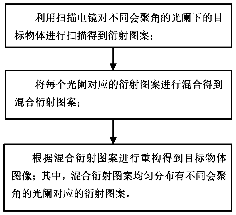
[0042] Combine figure 1 As shown, a scanning electron microscopy imaging method of the present invention uses a scanning electron microscope to scan target objects under apertures with different convergence angles to obtain diffraction patterns. It is worth noting that scanning is performed under apertures with different convergence angles. The frequency information obtained is different. The aperture radius with a smaller convergence angle mainly obtains low-frequency information, and the aperture radius with a larger convergence angle mainly obtains high-frequency information. Further, the diffraction patterns corresponding to each diaphragm are mixed to obtain a mixed diffraction pattern. It should be noted that the mixed diffraction pattern is uniformly distributed with the diffraction patterns corresponding to the diaphragms with different convergence angles, that is, each diaphragm in the mixed diffraction pattern The number of corresponding diffraction patterns is the sa...

Embodiment 2

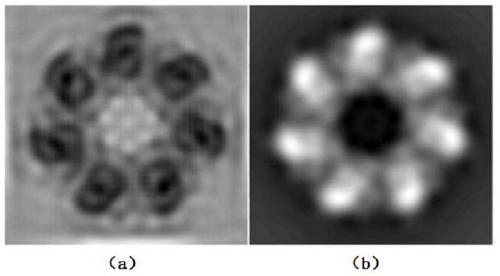
[0068] The content of this embodiment is basically the same as that of embodiment 1. This embodiment takes the simulated atomic potential field of biomolecules as the target object, the target object is a 2048x2048 complex number matrix, and the electron beam wave function generated by the circular aperture is used as the probe function , Is a complex number matrix of 1024x1024 size. The diaphragms selected in this embodiment are a circular diaphragm of 1mrad and a circular diaphragm of 10mrad. The defocus of the selected target object under the circular diaphragm of 1mrad is 1200nm, and the defocus is 1200nm under the circular diaphragm of 10mrad. The selected target object defocus is 120nm, which can ensure that the electron beam probe functions are similar in size at different convergence angles.

[0069] The probe function P can be obtained by the beam passing through the two apertures after propagation k (r) (k=1, 2), where k=1 is a 1mrad circular diaphragm, and k=2 is a 10m...

Embodiment 3

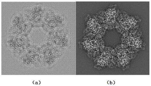
[0072] The content of this embodiment is basically the same as that of embodiment 1. The simulated atomic potential field of biomolecules and graphene is used as the target object. The target object is a complex matrix of 2048x2048 size, and the electron beam wave function generated by the circular aperture is used as the probe function. , Is a complex number matrix of 1024x1024 size. The diaphragms selected in this embodiment are a circular diaphragm of 1mrad and a circular diaphragm of 12mrad. The defocus of the target object selected under the circular diaphragm of 1mrad is 1200nm, and the defocus is 1200nm under the circular diaphragm of 12mrad. The selected target object defocus is 100nm, which can ensure that the electron beam probe functions are similar in size at different convergence angles.

[0073] The probe function P can be obtained by the beam passing through the two apertures after propagation k (r) (k=1, 2), where k=1 is a 1mrad circular diaphragm, and k=2 is a 10...


PUM


Abstract

The invention discloses a scanning electron microscopic imaging method, and belongs to the technical field of microscopic imaging. The scanning electron microscopic imaging method comprises the stepsof scanning the target object under the diaphragms with different convergence angles by using a scanning electron microscope to obtain a diffraction pattern; and mixing the diffraction patterns corresponding to the diaphragms to obtain a mixed diffraction pattern, performing multiple iterative calculations according to the mixed diffraction pattern to reconstruct O (r), taking the Oz (r) reconstructed by final iterative calculations as a final complex amplitude distribution function of the target object, and obtaining a reconstructed target object image according to the amplitude and phase ofthe Oz (r). The method aims to overcome the defects in the prior art. In order to overcome the defect that a diffraction pattern generated by a single diaphragm in a stacked imaging method can only obtain a reconstructed image of part of frequency band information of a target object, the invention provides a scanning electron microscopic imaging method which can obtain high-frequency characteristics and low-frequency characteristics of the target object, so that a clear and complete target object image can be obtained.

Description


Claims


Application Information

Patent Timeline
Owner NANJING UNIV
Why Eureka
Try Eureka