
Electrical construction suspender with automatic adjusting function

An automatic adjustment and electrical construction technology, applied in the direction of overhead line/cable equipment, etc., can solve the problems of high labor intensity of construction personnel, slow adjustment efficiency, and unsafe construction, and achieve the effect of fast fixing efficiency, convenient construction and safe construction.

Active Publication Date: 2020-05-19
IANGSU COLLEGE OF ENG & TECH
View PDF4 Cites 0 Cited by
  • Summary
  • Abstract
  • Description
  • Claims
  • Application Information

AI Technical Summary

Problems solved by technology

[0003] When in use, the construction personnel manually "rotate the threaded rod in the threaded pipe to adjust the distance between the support plate and the bracket, and then put the wires of the electrical wiring into the bracket". This method of adjusting the distance between the support plate and the bracket, Not only is the adjustment efficiency slow, but also due to the gravity of the support plate and the bracket itself, during the adjustment process, it is easy to cause labor-intensive and time-consuming problems for the construction personnel. , Temporarily fix the wires at a suitable position at a high place". Once the wind blows the hook during the construction process, it is easy to drive the hook to shake, and the wires of the electrical wiring are thrown out of the bracket. This fixing method is not only vulnerable to the external environment The influence of the influence on the wire fixing stability of the electrical wiring is not high, and it is easy to cause the construction to be not safe enough, which will easily affect the smooth progress of the construction

Method used


Image

  • Electrical construction suspender with automatic adjusting function
  • Electrical construction suspender with automatic adjusting function
  • Electrical construction suspender with automatic adjusting function

Examples


Embodiment

[0040] The following is attached Figure 1-8 The present invention is described in further detail.

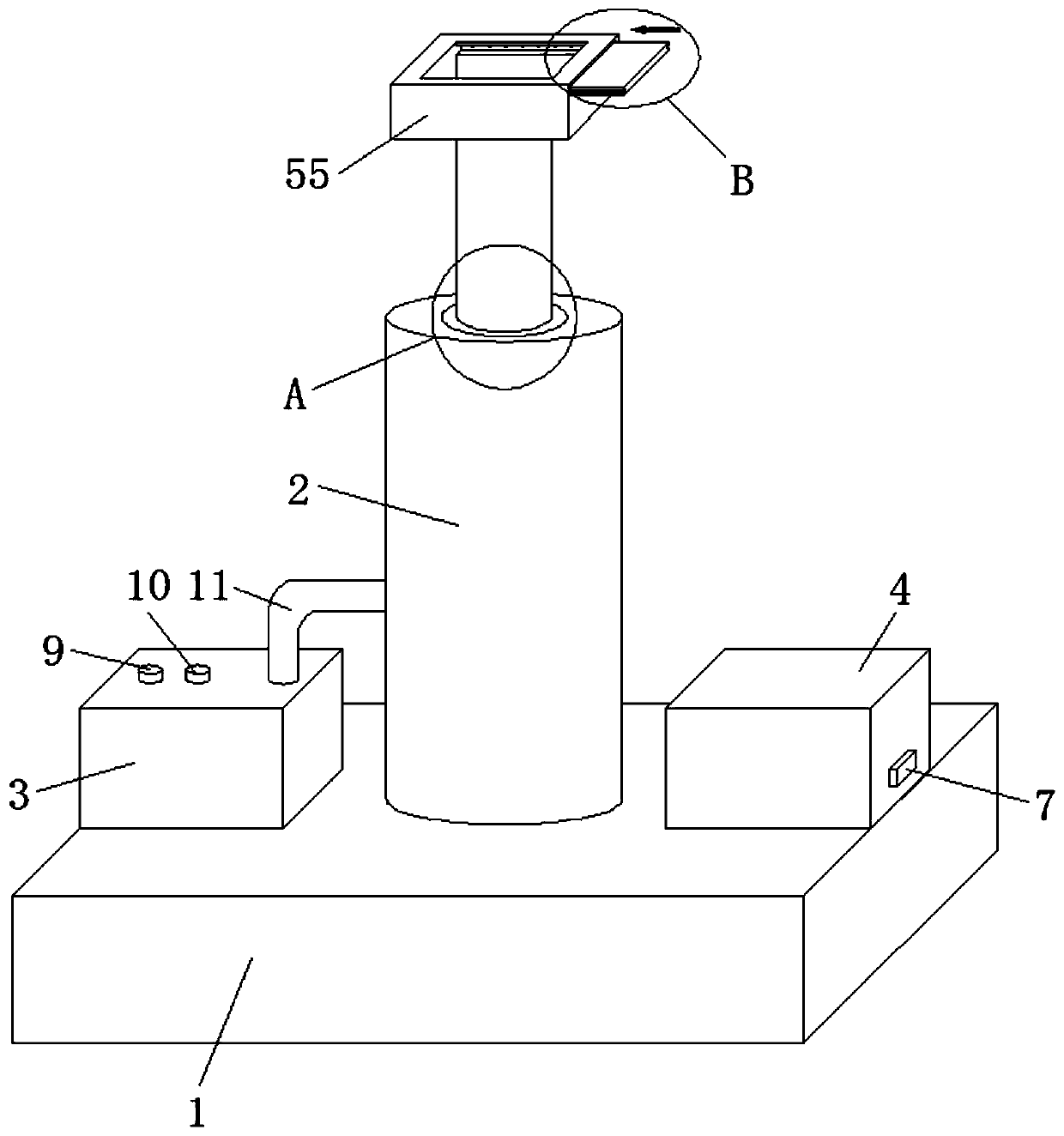
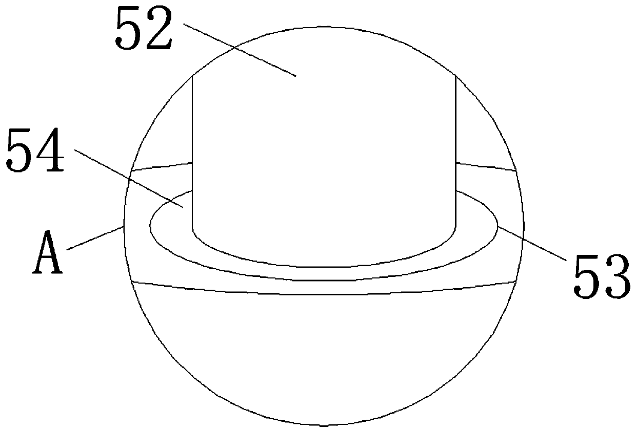
[0041] 一种具有自动调节功能的电气施工用吊杆,如 Figure 1-8As shown, including a support block 1, the upper surface of the support block 1 is respectively fixedly connected with a support rod 2, a small electric air pump 3 and a battery box 4, the support rod 2 is located between the small electric air pump 3 and the battery box 4, and the support rod 2 An automatic adjustment mechanism is provided inside, and the automatic adjustment mechanism includes a cavity 5, and the inside of the support rod 2 is provided with a cavity 5;

[0042] Such as figure 1 with Image 6 As shown, further, the small electric air pump 3 includes an air charging switch 9 and an air extraction switch 10, both the air charging switch 9 and the air extraction switch 10 are electrically connected to the small electric air pump 3, and the air outlet of the small electric air pump 3 is fixedly communicated with a L The t...


PUM


Abstract

The invention discloses an electrical construction suspender with an automatic adjusting function, which comprises a supporting block. A supporting rod, a small electric air pump and a battery box arefixedly connected to the upper surface of the supporting block, the supporting rod is located between the small electric air pump and the battery box, an automatic adjusting mechanism is arranged inthe supporting rod, and the automatic adjusting mechanism comprises a cavity. According to the electrical construction suspender with the automatic adjusting function, the automatic adjusting mechanism is arranged in the supporting rod,the automatic adjusting mechanism comprises a cavity, a cavity is formed in the supporting rod, and therefore, only one key is needed through the mechanism, an electric wire can be automatically and temporarily fixed at a high position, the whole fixing process is high in fixing efficiency and short in time consumption, the labor intensity of constructors is reduced, and meanwhile, the characteristics of being not influenced by the external environment, high in stability of fixing the electric wire for electrical wiring, safe in construction and convenient for smooth construction are achieved.

Description

technical field [0001] 本发明涉及电气设备技术领域,更具体地说,它涉及一种具有自动调节功能的电气施工用吊杆。 Background technique [0002] 如中国专利文献公开的一种电气施工用吊杆(申请号:201810236875.X),此专利虽然解决了实现将电线暂时固定在高处合适位置,安装好金具后再固定线路,让电气施工更加安全和高效的问题,但该装置在使用时,“该电气施工用吊杆在使用时可以先在螺纹管中旋转螺纹杆,从而调整好支撑盘和托架的距离,然后将电气布线的电线放入托架内部,绝缘内衬垫可以保障电线的绝缘性,工人可以利用吸盘吸附天花板,或者用吊钩勾住高处的物体,将电线暂时固定在高处合适位置,安装好金具后再固定线路,让电气施工更加安全和高效,此外,螺纹管上的TPE材质可用于将螺纹管加长使用,更加方便灵活”。 [0003] 使用时施工人员手动“先在螺纹管中旋转螺纹杆,从而调整好支撑盘和托架的距离,然后将电气布线的电线放入托架内部”,此调整支撑盘和托架距离的方法,不仅调整效率慢,而且因支撑盘和托架自身重力的作用,在调整过程中,易导致施工人员劳动强度大且用时过长的问题,同时,施工人员“用吊钩勾住高处的物体,将电线暂时固定在高处合适位置”,一旦在施工过程中有风吹动吊钩,易带动吊钩发生晃动,将电气布线的电线甩出托架,此固定方式,不仅易受外界环境的影响,对电气布线的电线固定的稳定性不高,而且,易导致施工不够安全,进而易影响施工的顺利进行的问题。 [0004] 所以,需要一种具有自动调节功能的电气施工用吊杆。 Contents of the invention [0005] 针对现有技术存在的不足,本发明的目的在于提供一种具有自动调节功能的电气施工用吊杆,其具有实现一键自动将电线暂时固定在高处,整个固定过程不仅固定效率快,而且用时少且减轻施工人员的劳动强度,同时,实现不仅不受外界环境的影响,对电气布线的电线固定的稳定性高,而且,施工安全且便于施工顺利进行的特点。 [0006] To achieve the above object, the present invention provides the following technical solutions: [0007] 一种具有自动调节功...

Claims


Application Information

Patent Timeline
IPC IPC(8): H02G1/04
CPCH02G1/04
Inventor 师阳
Owner IANGSU COLLEGE OF ENG & TECH
Learn More