Fire fighting device for large-people flow place and using method of fire fighting device

A fire-fighting device and place technology, which is applied in the field of fire-fighting devices in places with large crowds, can solve the problems of limited range of action of fire extinguishers and burns of users, and achieve the effect of preventing people from being burned and slowing down the moving speed

Inactive Publication Date: 2020-05-22
张玉同
6 Cites 0 Cited by

AI-Extracted Technical Summary

Problems solved by technology

[0003] In the prior art, some crowded places are usually equipped with multiple fire extinguishers. When a fire breaks out and the firefighters have not arrived at the scene, the fire situation is first controlled by t...

Method used

Please refer to Fig. 1-4, a kind of fire-fighting device that is used for large flow of people place, comprises support column 1, and the bottom end of support column 1 is fixedly installed with fixed base 2, and the bottom of fixed base 2 is fixedly connected with universal wheel 24, and the universal wheel 24 is provided with a brake mechanism, so that the fire fighting device is convenient to move to the vicinity of the fire source, and can be fixed by the brake mechanism on the universal wheel, and the outer wall of the support column 1 is provided with an annular rotation groove 3, On the outer wall of the support column 1 and rotate in the position and the rotating groove 3, a rotating ring 4 is installed. On the outer walls of the left and right sides of the rotating ring 4, a support rod 5 is fixedly installed. Case 6, the inner movable installation of device case 6 is provided with push plate 7, is fixedly connected with two high pressure springs 8 on the outer wall of push plate 7 one side, and the end of high pressure spring 8 away from push plate 7 is fixedly connected with the inwall of device case 6, And the high-pressure spring 8 is in a compressed state, so t...

Abstract

The invention discloses a fire fighting device for a large-people flow place and a using method of the fire fighting device, and belongs to the technical field of fire fighting. The fire fighting device for the large-people flow place comprises a supporting column, wherein a fixed base is fixedly installed at the bottom end of the supporting column, an annular rotating groove is formed in the outer wall of the supporting column, a rotating ring is rotationally installed on the outer wall of the supporting column and located in the rotating groove, supporting rods are fixedly installed on the outer walls of the left side and the right side of the rotating ring, device boxes are fixedly installed at the ends, away from the rotating ring, of the supporting rods, push plates are movably installed in the device boxes, and two high-pressure springs are fixedly connected to the outer wall of one side of each push plate, and dampers are fixedly mounted in the device boxes. According to the fire fighting device and the using method, after simple operation, the fire fighting device can automatically spray fire extinguishing liquid for a certain period of time without being held by hands, thefire fighting device does not need to be close to a fire source all the time, personnel can be effectively prevented from being burnt, the fire fighting device can be used without being powered on, and the situation that the fire fighting device cannot be used due to power failure caused by fire disasters is avoided.

Application Domain

Technology Topic

Image

  • Fire fighting device for large-people flow place and using method of fire fighting device
  • Fire fighting device for large-people flow place and using method of fire fighting device
  • Fire fighting device for large-people flow place and using method of fire fighting device

Examples

  • Experimental program(1)

Example Embodiment

[0046] Example 1:
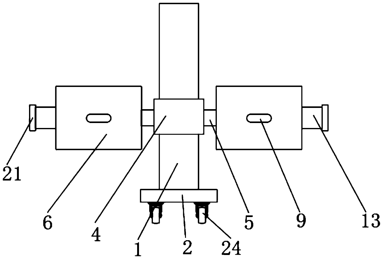
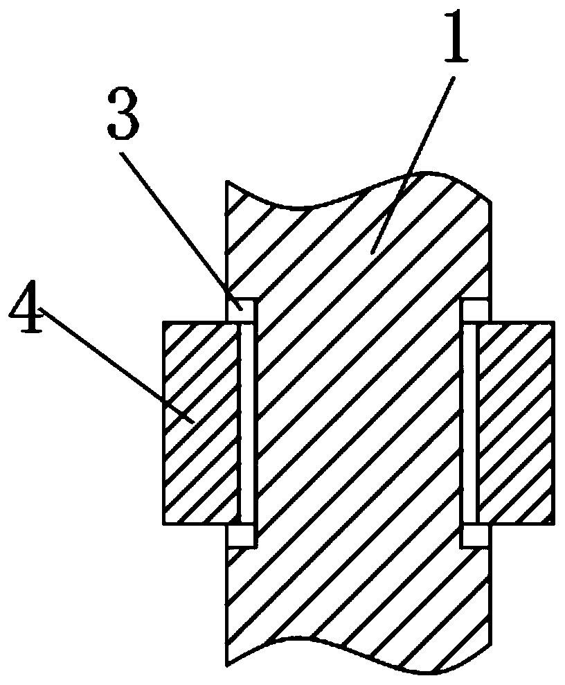
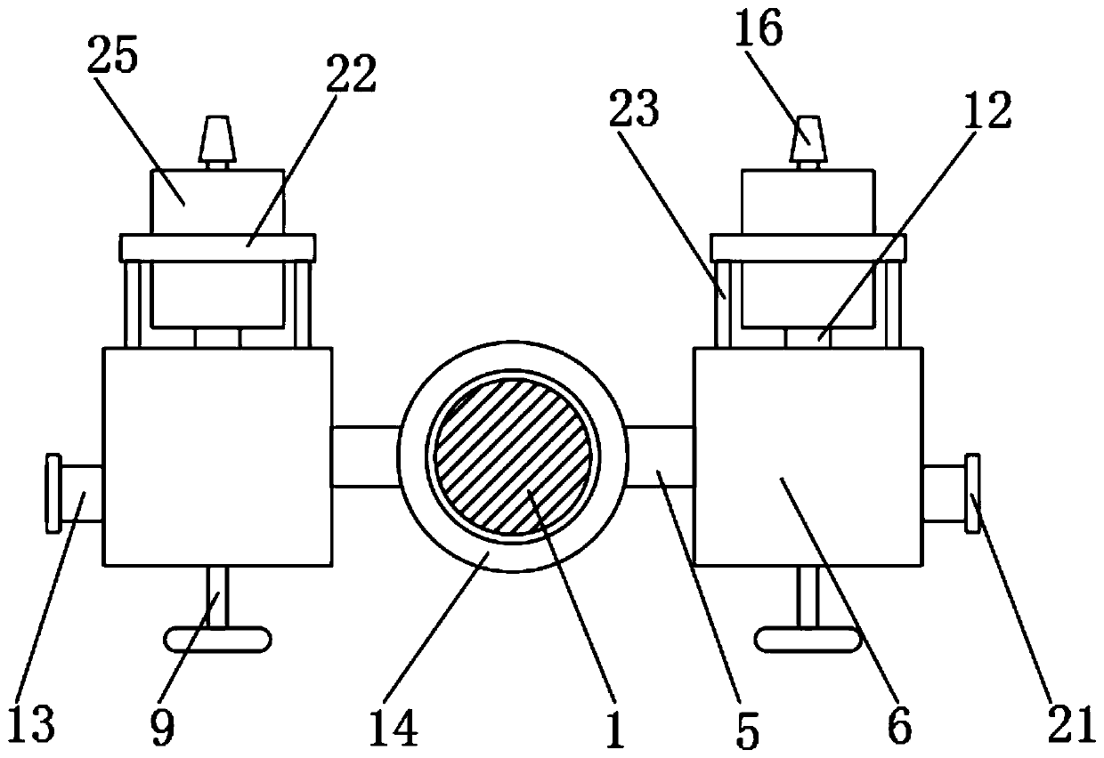
[0047] see Figure 1-4 , a kind of fire-fighting device that is used for large crowd flow place, comprises support column 1, and the bottom end of support column 1 is fixedly installed with fixed base 2, and the bottom of fixed base 2 is fixedly connected with universal wheel 24, and universal wheel 24 is provided with There is a brake mechanism, so that the fire-fighting device is convenient to move to the vicinity of the fire source, and can be fixed by the brake mechanism on the universal wheel. The outer wall of the support column 1 is provided with an annular rotation groove 3, and the outer wall of the support column 1 is located in the same position as the A rotating ring 4 is installed in the rotating groove 3, and a support rod 5 is fixedly installed on the outer walls of the left and right sides of the rotating ring 4. The end of the supporting rod 5 away from the rotating ring 4 is fixedly installed with a device box 6, and the internal activities of the device case 6 Push plate 7 is installed, and two high-pressure springs 8 are fixedly connected on the outer wall of push plate 7 one side, and one end of high-pressure spring 8 is away from push plate 7 and is fixedly connected with the inwall of device case 6, and high-pressure spring 8 is in compressed state, makes When the high-pressure spring 8 rebounds, it will push the push plate 7 away from the side of the pull rod 9, and it will be driven by the elastic force of the high-pressure spring 8 without power on, so it will not be affected by power failure. The pull rod 9 fixedly connected on the outer wall of the push plate 7 is set to a T shape, and the pull rod 9 runs through the outer wall of the device box 6 and is slidably connected with the device box 6, so that after the fire is over, the pull rod 9 can be pulled to make the The push plate 7 resets, and the interior of the device box 6 is fixedly equipped with a damper 11. The damper 11 is located on the side of the push plate 7 away from the high-pressure spring 8, and the damping end of the damper 11 is fixedly connected with the push plate 7. Through the damper 11 The setting of can slow down the moving speed of push plate 7, and then make the eruption of fire extinguishing agent sustainable certain hour, push plate 7 is fixedly connected with push rod 12 on the outer wall away from high pressure spring 8 side.
[0048] see figure 1 and Figure 5-6 , the outer wall of the device box 6 away from the side of the support rod 5 is fixedly installed with a fixed cylinder 13, and the inside of the fixed cylinder 13 is movably installed with a clamping rod 14, and the outer wall of the push plate 7 near the fixed cylinder 13 side is provided with a card slot 15, Draw bar 14 runs through the outer wall of device case 6 and is flexibly connected with draw-in groove 15, and draw-in bar 14 is fixedly connected with pull ring 20 away from draw-in groove 15, by the setting of draw-in bar 14, draw-in groove 15, draw draw bar 14, make Draw bar 14 breaks away from draw-in groove 15, can remove the restriction to push plate 7, thereby push plate 7 moves under the effect of high pressure spring 8 elastic force, the setting of draw ring 20 can be convenient to pull draw bar 14, draw bar 14 The outer walls on the upper and lower sides are fixedly connected with a restriction rod 17, and the right side of the restriction rod 17 is provided with a restriction block 18 fixedly installed on the inner wall of the fixed cylinder 13, and the clamp rod 14 runs through the restriction block 18 and is slidably connected with the restriction block 18. And the through groove 19 is vertically arranged with the restricting rod 17, through the setting of the restricting block 18, the restricting rod 17 and the through groove 19, the clamping rod 14 is rotated 90° earlier, so that the restricting rod 17 is parallel to the through groove 19, and the pull bar 9 can be pulled. And then to prevent the clamping rod 14 from accidentally disengaging, causing waste of fire extinguishing agent, the inside of the restriction block 18 is provided with two through grooves 19 that run through the restriction block 18, and the outer wall of the fixed cylinder 13 away from the device box 6 side is threadedly connected with a cylinder cover 21 , Rotate and twist the cylinder cover 21, the cylinder cover 21 can be taken off.
[0049] see Figure 3-4 , the side of the device box 6 away from the pull rod 9 is fixedly equipped with a piston cylinder 25, the outer wall of the piston cylinder 25 is fixedly connected with a connecting ring 22, and both sides of the piston cylinder 25 are provided with a connecting rod 23 fixedly connected to the connecting ring 22 , the end of the connecting rod 23 away from the connecting ring 22 is fixedly connected with the device case 6, the piston cylinder 25 is fixedly installed on one side of the device case 6 through the connecting ring 22 and the connecting rod 23, and the piston 10 is movable inside the piston cylinder 25, and the piston The outer wall of the cylinder 25 away from the device box 6 is fixedly connected with a nozzle 16, the nozzle 16 communicates with the inside of the piston cylinder 25, the inside of the piston cylinder 25 is filled with fire extinguishing agent, and the end of the push rod 12 away from the push plate 7 penetrates the device. The outer wall of the box 6 and the piston cylinder 25 extends to the side of the piston 10, and the nozzle 16 is provided with a valve. Through the setting of the push rod 12, the piston cylinder 25, the piston 10 and the nozzle 16, the valve on the nozzle 16 is opened, and when the rod is stuck After 14 breaks away from the draw-in groove 15, the high-pressure spring 8 drives the push plate 7 to move, and the push plate 7 pushes the piston 10 through the push rod 12, so that the fire extinguishing agent in the piston barrel 25 is automatically ejected through the nozzle 16, so that the user does not need to hold it, and It is not necessary to be close to the fire source all the time, thereby preventing the user from being burned.
[0050] A method for using a fire-fighting device in a place with large crowds, comprising the following steps:
[0051] S1, move the support column 1 to the vicinity of the fire source, and lock the universal wheel 24;
[0052] S2, rotate the device box 6 through the pull rod 9, so that the nozzle 16 is aligned with the fire source;
[0053] S3. Rotate and unscrew the cylinder cover 21, rotate the clamping rod 14 through the pull ring 20 to rotate the clamping rod 14 by 90°, and pull out the clamping rod 14 to disengage the clamping rod 14 from the clamping groove 15;
[0054] S4, quickly open the valve on the nozzle 16, the fire extinguishing agent can be sprayed automatically, and the user can leave the vicinity of the fire source to prevent being burned.
[0055] The present invention provides a kind of fire-fighting device that is used in the place of big flow of people, and this fire-fighting device is set by universal wheel 24, makes fire-fighting device be convenient to move to near the fire source, and can be fixed by the brake mechanism on the universal wheel; The high-pressure spring 8 is set so that when the high-pressure spring 8 rebounds, it will push the push plate 7 away from the side of the pull rod 9; through the setting of the pull rod 9, after the fire is over, the push plate 7 can be reset by pulling the pull rod 9 ; By the setting of the damper 11, the moving speed of the push plate 7 can be slowed down, so that the eruption of the fire extinguishing agent can last for a certain period of time; Break away from draw-in groove 15, can remove the restriction to push plate 7, thereby make push plate 7 move under the effect of high pressure spring 8 elastic force, the setting of draw ring 20 can be convenient to pull draw bar 14; For the setting of rod 17 and through groove 19, the clamp rod 14 is rotated 90° first, so that the limiting rod 17 is parallel to the through groove 19, and then the pull rod 9 can be pulled, thereby preventing the clamp rod 14 from accidentally detaching, causing waste of fire extinguishing agent; 12. The piston cylinder 25, the piston 10, and the nozzle 16 are set. Open the valve on the nozzle 16. When the lever 14 is out of the groove 15, the high-pressure spring 8 drives the push plate 7 to move, and the push plate 7 pushes the piston 10 through the push rod 12. , so that the fire extinguishing agent in the piston cylinder 25 is automatically ejected through the nozzle 16, so that the user does not need to hold it by hand, and does not need to be close to the fire source all the time, thereby preventing the user from being burned; The method is simple to operate, and can quickly turn on the fire-fighting device to spray the fire extinguishing agent; compared with the existing technology, it can realize that the fire extinguishing liquid can be sprayed automatically after a simple operation, and the spray can continue for a certain period of time, without the need for hand-holding or close proximity The fire source can effectively prevent people from being burned, and it can be used without power on, and it will not be unusable due to power failure caused by fire.

PUM

no PUM

Description & Claims & Application Information

We can also present the details of the Description, Claims and Application information to help users get a comprehensive understanding of the technical details of the patent, such as background art, summary of invention, brief description of drawings, description of embodiments, and other original content. On the other hand, users can also determine the specific scope of protection of the technology through the list of claims; as well as understand the changes in the life cycle of the technology with the presentation of the patent timeline. Login to view more.

Similar technology patents

Blueprint cloth production equipment

InactiveCN109501445ASlow downLong application timeRotary pressesPrinting press partsBlueprintCoating
Owner:磐安县宸熙工艺品有限公司

Low-noise subway vehicle door pneumatic auxiliary lock

PendingCN114086841ASlow downReduce working noisePneumatic/hydraulic locking circuitsHydraulic/pneumatic locking actuatorsCar doorElectromagnetic valve
Owner:CRRC NANJING PUZHEN CO LTD

Classification and recommendation of technical efficacy words

Why Eureka
Try Eureka