
Front windshield sun-shading device

A technology of front windshield and sunshade device, applied in windshield, anti-glare equipment, transportation and packaging, etc., can solve the problems of low degree of automation, difficult for occupants to sit, unable to block sunlight, etc. Stable state and good shading effect

Pending Publication Date: 2020-05-22
SHANGHAI COTECH AUTOMOTIVE ENG CORP LTD
View PDF0 Cites 0 Cited by
  • Summary
  • Abstract
  • Description
  • Claims
  • Application Information

AI Technical Summary

Problems solved by technology

[0002] With the improvement of people's quality of life, cars are becoming more and more common. In summer, cars are exposed to the sun after parking. The front windshield of the car cannot block the sun due to its high transparency, which causes the temperature inside the car to rise, making the seats especially exposed to the sun. Raising the temperature of the seat makes it difficult for the occupants to sit, making it necessary to cool down the interior of the car when driving the car again, and the front windshield glass is unobstructed, and the privacy is not good. Some drivers do not want to expose the environment inside the car. Now many vehicles There is a blocking device at the front windshield
[0003] Most of the sunshade devices for the front windshield on the existing market are of the up-and-down type, and the sunshade needs to be pulled down manually. However, since the front windshield is installed at an angle, the up-and-down sunshade can only be pulled down vertically , can not fit with the front windshield, resulting in the space between the front windshield and the vertical sunshade cloth will still be exposed to the sun, not only affect the effect of sunshade, but also not beautiful enough, and it will take up a lot of space, making the interior of the car It is very inconvenient for personnel activities, and manual operation is required, and the degree of automation is low

Method used


Image

  • Front windshield sun-shading device
  • Front windshield sun-shading device
  • Front windshield sun-shading device

Examples


Embodiment Construction

[0025] The present invention will be described in detail below in conjunction with the accompanying drawings and specific embodiments. This embodiment is carried out on the premise of the technical solution of the present invention, and detailed implementation and specific operation process are given, but the protection scope of the present invention is not limited to the following embodiments.

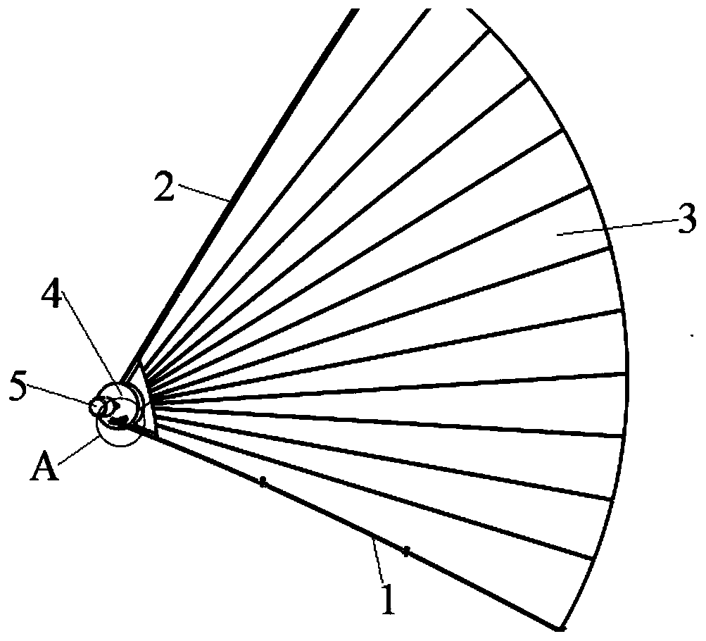
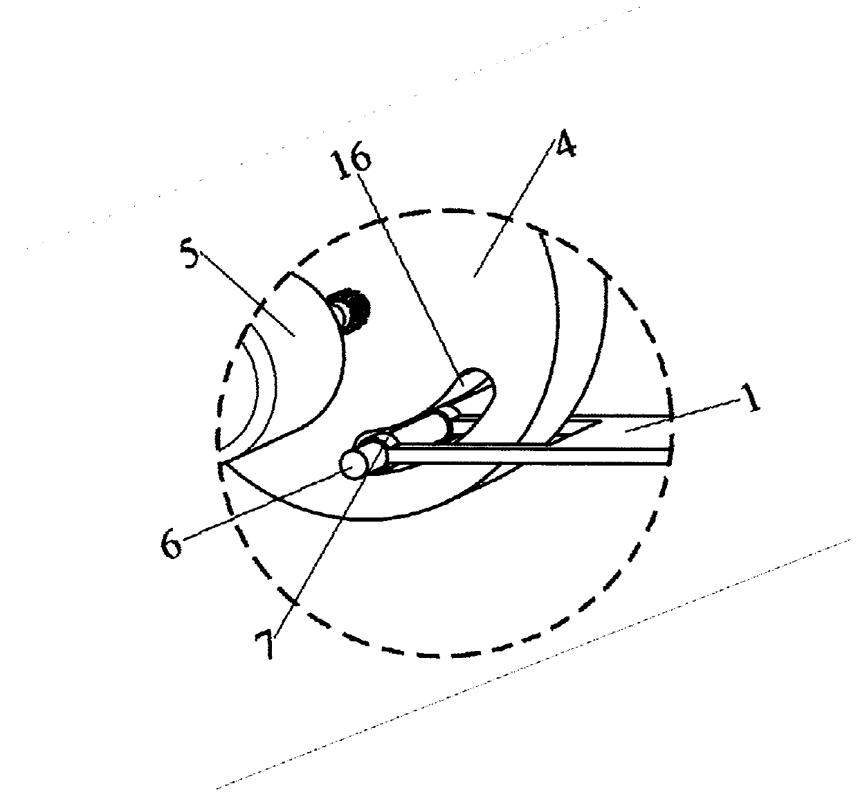
[0026] An electric front windshield sunshade device, such as Figure 4 with Figure 5 , including 1 pair of folding fans and 1 pair of magnets 12, 1 pair of folding fans are symmetrically arranged and located on the instrument panel 11 inside the front windshield 9, as figure 1 with figure 2 , the folding fan includes a lower connecting plate 1, an upper connecting plate 2, fan blades 3 and an electric two-way motor 5, the upper connecting plate 2 is made of metal material and one end thereof is fixedly connected with a turntable 4, and the electric two-way motor 5 and the turntabl...


PUM


Abstract

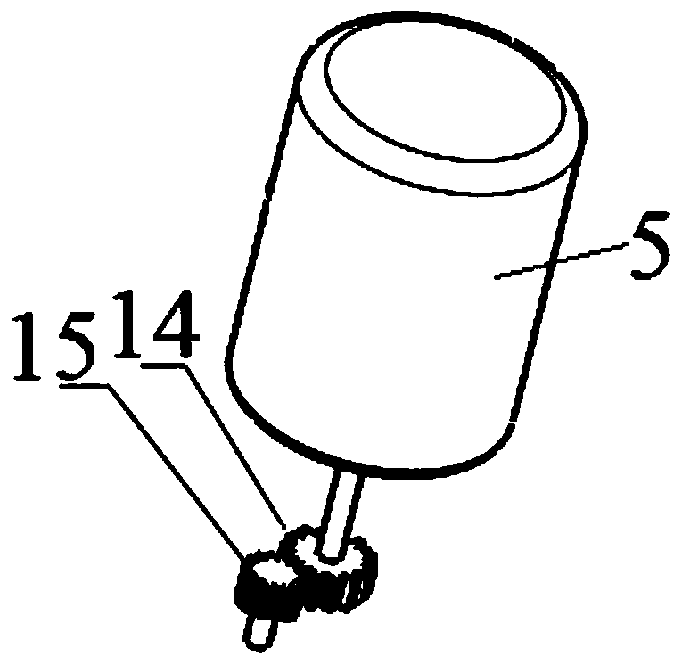
The invention relates to an electric front windshield sun-shading device which comprises a pair of folding fans and a pair of magnets (12). The folding fans are symmetrically arranged on a vehicle body. Each folding fan comprises a lower connecting plate (1), an upper connecting plate (2), fan blades (3) and an electric two-way motor (5). The upper connecting plates (2) are made of a metal material, and one end of each upper connecting plate (2) is fixedly connected with a turntable (4). The electric two-way motors (5) and the turntables (4) are both fixed on the vehicle body. The lower connecting plates (1) are fixed on the vehicle body, and one end of each lower connecting plate (1) is hinged to the corresponding turntable (4). A coaxial driven gear (15) is fixed on each turntable (4), arotating shaft of each electric two-way motor (5) is sleeved with a driving gear (14), and the driven gears (15) are meshed with the driving gears (14). The magnets (12) are symmetrically arranged onthe vehicle body. Compared with the prior art, the device has the advantages of simple structure, good stability, high speed and the like.

Description

technical field [0001] The invention relates to the field of automotive interior parts, in particular to a sunshade device for a front windshield. Background technique [0002] With the improvement of people's quality of life, cars are becoming more and more common. In summer, cars are exposed to the sun after parking. The front windshield of the car cannot block the sun due to its high transparency, which causes the temperature inside the car to rise, making the seats especially exposed to the sun. Raising the temperature of the seat makes it difficult for the occupants to sit, making it necessary to cool down the interior of the car when driving the car again, and the front windshield glass is unobstructed, and the privacy is not good. Some drivers do not want to expose the environment inside the car. Now many vehicles There is a blocking device at the front windshield. [0003] Most of the sunshade devices for the front windshield on the existing market are of the up-and...

Claims


Application Information

Patent Timeline
Patent Type & Authority Applications(China)
IPC IPC(8): B60J1/20B60J3/00
CPCB60J1/2091B60J3/00
Inventor 唐才武姜忠玉谢益松
Owner SHANGHAI COTECH AUTOMOTIVE ENG CORP LTD
Learn More