A control system, an ignition system, and an ignition charging control method
A control system and ignition coil technology, applied in the direction of induction energy storage devices, etc., can solve the problem of inaccurate charging time of the ignition coil
- Summary
- Abstract
- Description
- Claims
- Application Information
AI Technical Summary
Problems solved by technology
Method used
Image
Examples
Embodiment 1
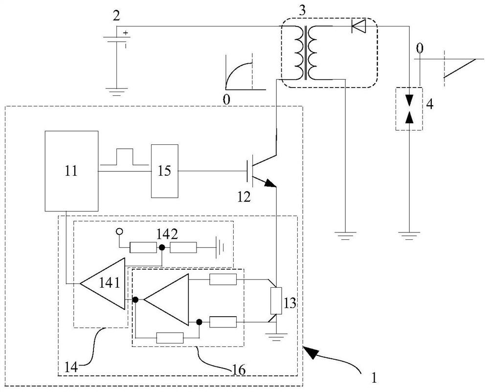
[0059] Please refer to image 3 , an embodiment of the present invention provides a control system 1 for controlling the charging of an ignition coil, the control system 1 includes: a micro-control unit 11 , a driver-level switch 12 , a detection resistor 13 and a comparison unit 14 that are connected in sequence to form a control loop . Optionally, the number of the control loops is n, the n control loops include n the driving stage switches 12, the n control loops share the micro-control unit 11, and n is a natural number, For example, n can be 1, 2, 4, 6, or 8, etc. The embodiment of the present invention is described for the case where n is equal to 1; The detection resistor 13 and a comparison unit 14 form a detection circuit.
[0060] The comparison unit 14 is used to compare the voltage across the detection resistor 13 with a reference voltage Vref, and output a signal representing the charging current level of the ignition coil to the micro-control unit 11 according ...
Embodiment 2
[0078] The difference from the first embodiment is that in the embodiment of the present invention, the control loop is connected to the primary of the ignition coil 3 through the detection resistor 13, such as Figure 5 As shown, the gate of the IGBT of the driving stage switch 12 is connected to the pre-drive circuit 15 , the collector is connected to one end of the detection resistor 13 , and the emitter is grounded.
[0079] In addition, compared with the first embodiment, the control system 1 of the embodiment of the present invention must include a differential operational amplifier 16 to make a difference between the voltages across the detection resistor 13 and then amplify and input the voltage to the comparison unit 14, and the embodiment of the present invention needs to be in all An additional protection circuit (protection circuit) is added to the input of the differential operational amplifier 16 Figure 5 not shown) to keep the control loop from being damaged in...
Embodiment 3
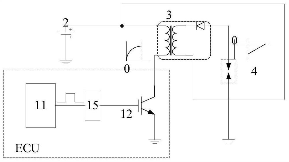
[0081] The difference from the second embodiment is that in the embodiment of the present invention, the ignition coil 3 is primarily located between the detection resistor 13 in the control system 1 and the driving stage switch IGBT 12 , and the detection resistor 13 is connected to the The connecting end of the comparison unit 14 in the control system 1 is also connected to the battery 2 . Please refer to the specific connection relationship. Image 6 . Since the collector of the IGBT is directly connected to the primary of the ignition coil in the implementation of the present invention, there is no need to add an additional protection circuit, but two additional wires need to be introduced from outside the control system to be connected to both ends of the detection resistor 13 to detect all the the voltage across the detection resistor 13.
PUM
 Abstract
Description
Claims
Application Information
 - R&D
- Intellectual Property
- Life Sciences
- Materials
- Tech Scout
- Unparalleled Data Quality
- Higher Quality Content
- 60% Fewer Hallucinations
Browse by: Latest US Patents, China's latest patents, Technical Efficacy Thesaurus, Application Domain, Technology Topic, Popular Technical Reports.
© 2025 PatSnap. All rights reserved.Legal|Privacy policy|Modern Slavery Act Transparency Statement|Sitemap|About US| Contact US: help@patsnap.com


