Charge control device and charge control method

a control device and charge control technology, applied in secondary cell servicing/maintenance, instruments, electrochemical generators, etc., can solve the problems of long charge time, complex map, and consuming electric power of batteries, so as to estimate the charge time accurately, the charge time can be accurately estimated, and the calculation is easy to make.

Pending Publication Date: 2022-10-06
HONDA MOTOR CO LTD
View PDF0 Cites 0 Cited by
  • Summary
  • Abstract
  • Description
  • Claims
  • Application Information

AI Technical Summary

Benefits of technology

[0014]According to this aspect, since the charge time is estimated by taking into account the temperature and the electric power consumption of the battery, the charge time can be estimated accurately. In addition, even when there are various auxiliary devices, the electric power consumption of each individual auxiliary device is not taken into account but instead, the electric power consumption of the all auxiliary devices is taken into account, and therefore, the calculation can be made easily.
[0015]According to the foregoing configuration, it is possible to provide a charge control device and a charge control method which can estimate the charge time accurately.

Problems solved by technology

However, even during charging, one or more auxiliary devices such as a temperature adjustment device may be driven so that the electric power of the battery is consumed.
In this case, there is a problem that the actual charge time becomes longer than the charge time displayed on the display device.
To solve this problem, it may be conceived to prepare a map beforehand taking into account the power consumption by the auxiliary devices, but it requires to take into account various use states of the multiple auxiliary devices, and this creates a problem that the map becomes complicated and the amount of data increases.

Method used


Image

  • Charge control device and charge control method
  • Charge control device and charge control method
  • Charge control device and charge control method

Examples


Embodiment Construction

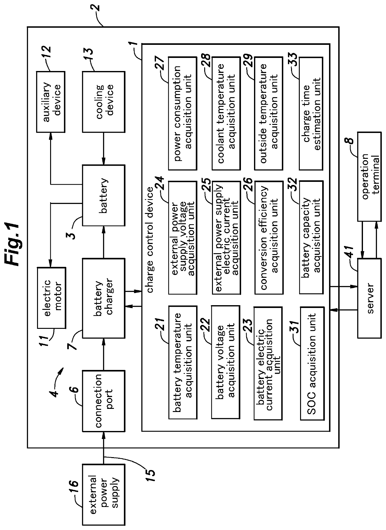
[0021]In the following, an embodiment of a charge control device 1 according to the present invention will be described. The charge control device 1 controls charging of the battery 3 installed in a vehicle 2 such as an electric car or a plug-in hybrid vehicle.

[0022]As shown in FIG. 1, a battery system 4 includes a battery 3, a connection port 6, a battery charger 7, and an operation terminal 8, in addition to the charge control device 1. The battery 3 includes multiple cells such as lithium ion battery cells. The multiple cells are connected in series or in parallel with each other. The battery 3 supplies electric power to an electric motor 11, which is a drive source of the vehicle 2, and to various auxiliary devices 12. Also, the battery 3 is charged by receiving regenerative electric power from the electric motor 11 and electric power from an external power supply 16.

[0023]The battery 3 is provided with a cooling device 13. The cooling device 13 has a coolant circulation flow pa...


PUM


Abstract

A charge control device for charging a battery with electric power supplied from an external power supply includes: an external power supply information acquisition unit that acquires external power supply information including a voltage of the external power supply; a battery information acquisition unit that acquires battery information including a temperature, a voltage, and an electric current of the battery; a power consumption acquisition unit that acquires an amount of electric power supplied from the battery to an auxiliary device as a power consumption amount; and a charge time estimation unit that estimates a charge time of the battery. The charge time estimation unit acquires an initial value of a state of charge of the battery based on the battery information, and estimates the charge time based on the battery temperature, the external power supply information, the power consumption amount, and the initial value of the state of charge.

Description

TECHNICAL FIELD[0001]The present invention relates to a charge control device and a charge control method.BACKGROUND ART[0002]WO2014 / 046233A1 discloses a charge control device for a vehicle that acquires a charge time by referring to multiple maps based on a charging electric power, a battery temperature, and a state of charge (SOC), and displays the charge time on a display device.[0003]However, even during charging, one or more auxiliary devices such as a temperature adjustment device may be driven so that the electric power of the battery is consumed. In this case, there is a problem that the actual charge time becomes longer than the charge time displayed on the display device. To solve this problem, it may be conceived to prepare a map beforehand taking into account the power consumption by the auxiliary devices, but it requires to take into account various use states of the multiple auxiliary devices, and this creates a problem that the map becomes complicated and the amount o...

Claims


Application Information

Patent Timeline
Patent Type & Authority Applications(United States)
IPC IPC(8): H02J7/00G01R31/3842G01R31/374
CPCH02J7/00036H02J7/0049H02J7/0063G01R31/3842G01R31/374H02J7/007194H02J7/00712H02J7/007182H01M10/44H01M10/443H02J7/0047H02J7/0071H02J7/0068H02J7/00032
Inventor OGASAWARA, KOTASAITA, AKIRAOGAKI, TORU
Owner HONDA MOTOR CO LTD
Why Eureka
Try Eureka