Control system, ignition system and ignition charging control method

A control system and ignition coil technology, applied in the direction of inductive energy storage devices, etc., can solve the problem that the charging time of the ignition coil is not accurate enough.

Active Publication Date: 2020-05-22
UNITED AUTOMOTIVE ELECTRONICS SYST
View PDF7 Cites 2 Cited by
  • Summary
  • Abstract
  • Description
  • Claims
  • Application Information

AI Technical Summary

Problems solved by technology

[0009] The purpose of the present invention is to provide a control system, an ignition system and an ignition charging control method to solve the problem that the charging time of the existing ignition coil is not accurate enough

Method used


Image

  • Control system, ignition system and ignition charging control method
  • Control system, ignition system and ignition charging control method
  • Control system, ignition system and ignition charging control method

Examples


Embodiment 1

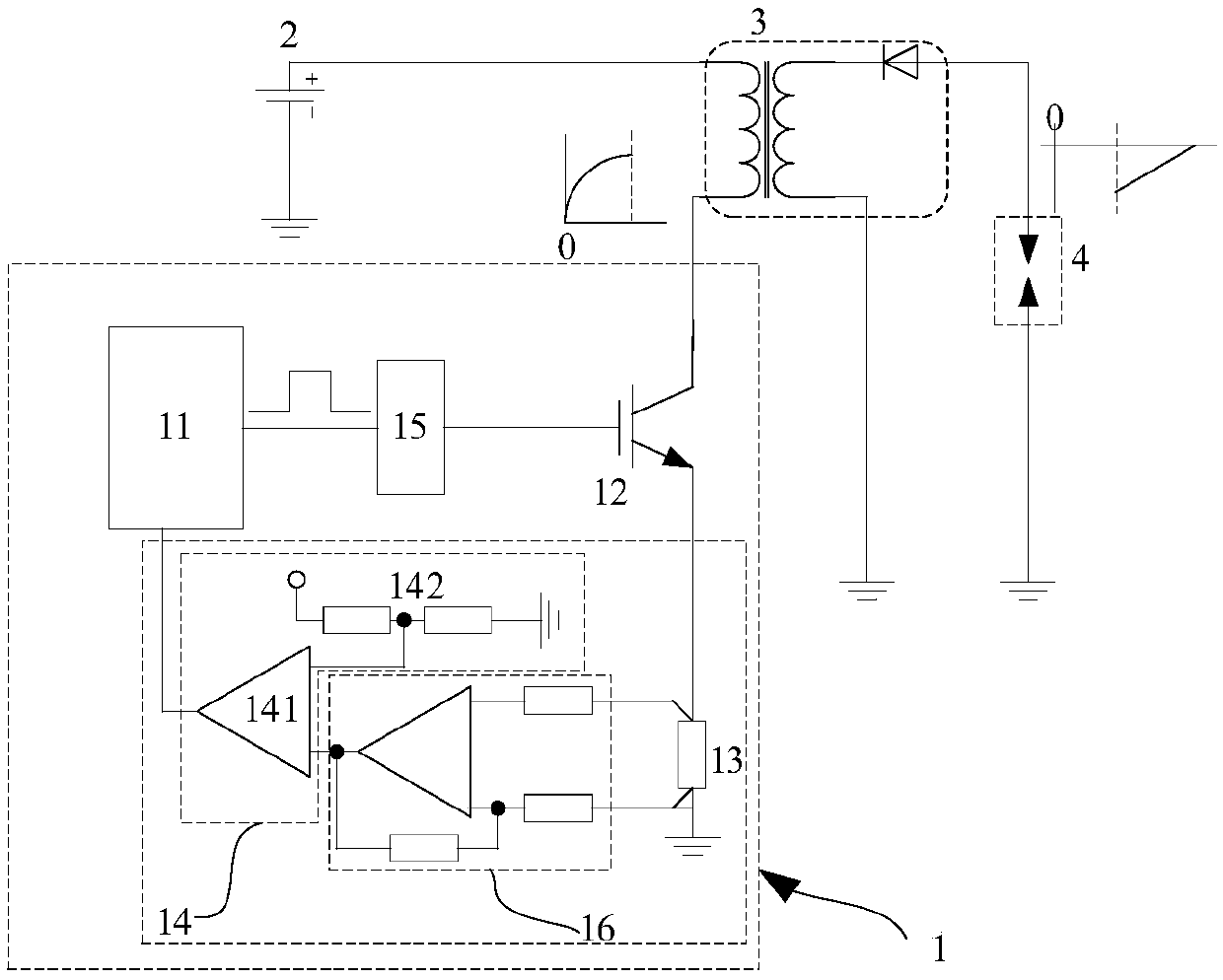
[0059] Please refer to image 3 The embodiment of the present invention provides a control system 1 for controlling the charging of the ignition coil. The control system 1 includes: a micro-control unit 11 connected in sequence to form a control loop, a driver stage switch 12, a detection resistor 13 and a comparison unit 14 . Optionally, the number of the control loops is n, and the n control loops include n the driver stage switches 12, and the n control loops share one micro control unit 11, and n is a natural number, For example, n can be 1, 2, 4, 6 or 8, etc., and the embodiment of the present invention is described for the case where n is equal to 1; the number of the detection resistor 13 and the number of the comparison unit 14 are equal and both are 1, one The detection resistor 13 and a comparison unit 14 form a detection circuit.

[0060] The comparison unit 14 is used to compare the voltage across the detection resistor 13 with a reference voltage Vref, and outpu...

Embodiment 2

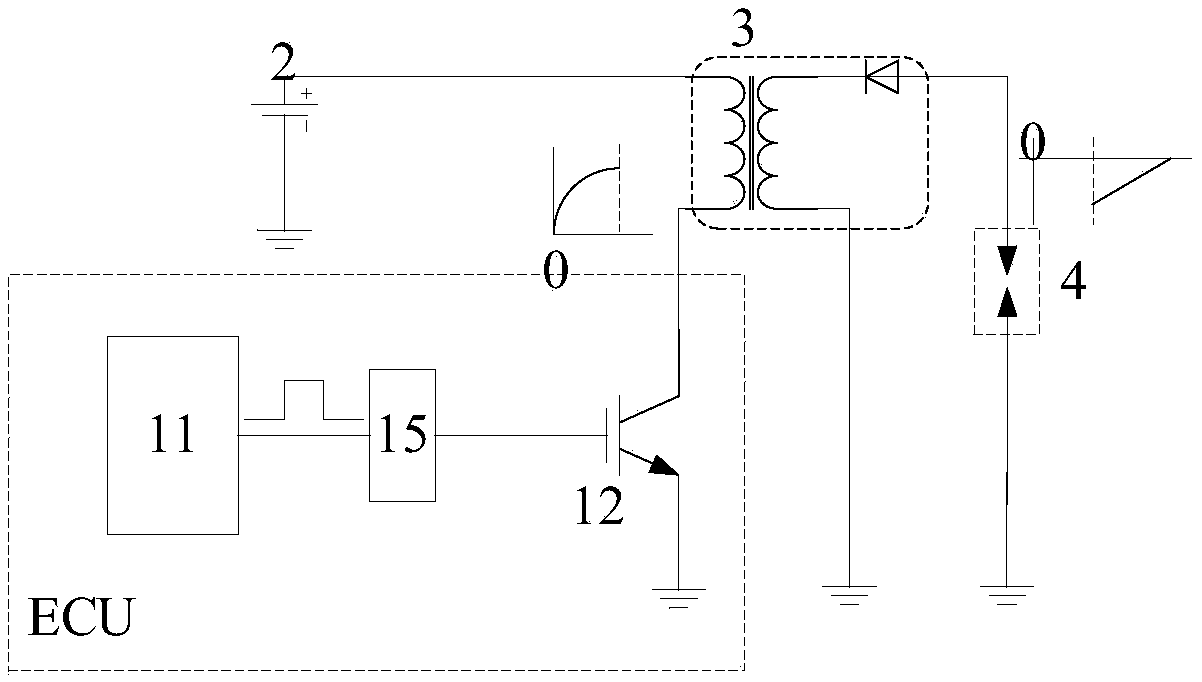
[0078] The difference from Embodiment 1 is that in the embodiment of the present invention, the control loop is connected to the primary stage of the ignition coil 3 through the detection resistor 13, such as Figure 5 As shown, the gate of the IGBT of the driving stage switch 12 is connected to the pre-driver circuit 15 , the collector is connected to one end of the detection resistor 13 , and the emitter is grounded.

[0079] In addition, compared with Embodiment 1, the control system 1 of the embodiment of the present invention must include a differential operational amplifier 16 to make a difference between the voltages across the detection resistor 13 and then amplify it before inputting it to the comparison unit 14. The input terminal of the above-mentioned differential operational amplifier 16 is added additional protection circuit (protection circuit Figure 5 not shown), in order to keep the control loop from being damaged under the condition of high voltage generated...

Embodiment 3

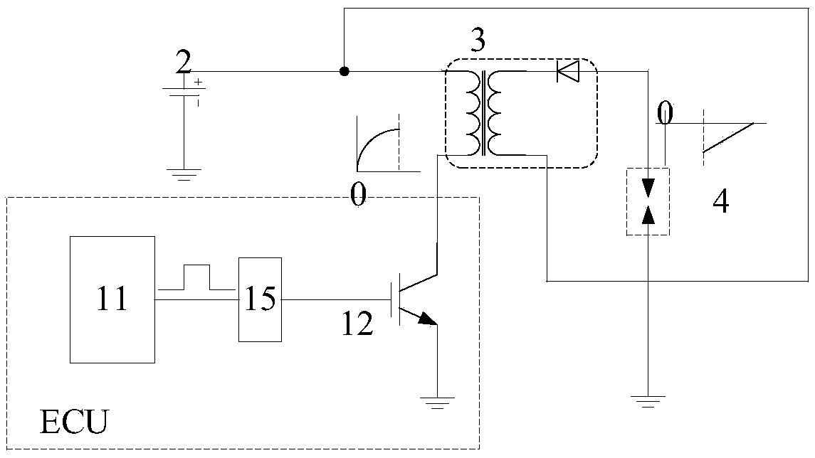
[0081] The difference from the second embodiment is that in the embodiment of the present invention, the primary of the ignition coil 3 is located between the detection resistor 13 in the control system 1 and the driving stage switch IGBT12, and the detection resistor 13 and the The connection end of the comparison unit 14 in the control system 1 is also connected to the battery 2, please refer to the specific connection relationship Figure 6 . Since the collector of the IGBT is directly connected to the primary of the ignition coil in the implementation of the present invention, there is no need to add an additional protection circuit, but it is necessary to introduce two additional wires from the outside of the control system to be connected to both ends of the detection resistor 13 for detection. The voltage across the sensing resistor 13.


PUM


Abstract

The invention provides a control system, an ignition system and an ignition charging control method. The ignition system comprises the control system, a battery, an ignition coil and a spark plug. Thecontrol system comprises a micro-control unit, a driving stage switch, a detection resistor and a comparison unit. The comparison unit is used for outputting a signal representing the charging current level to the micro-control unit by comparing the voltage at the two ends of the detection resistor and the reference voltage. The micro-control unit is used for processing the signal to adjust the charging time of the charging coil so that the charging time of the ignition coil can be more accurate, and therefore the phenomenon that the practical charging time is too large, the charging currentis too large, and consequently the driving stage switch or the ignition coil is damaged is avoided, and the phenomenon that the practical charging time is too short, the charging current is too small,and consequently the ignition energy is insufficient is avoided.

Description

technical field [0001] The invention relates to the technical field of automobile engines, in particular to a control system, an ignition system and an ignition charging control method. Background technique [0002] The ignition system of a modern automobile engine mainly includes: a battery, an electronic controller (ECU), a drive stage switch, an ignition coil, and a spark plug. The ECU collects the sensor signals installed in different parts of the engine and the vehicle, and selects the appropriate ignition energy to ignite the engine at the best time according to the operating conditions of the engine. The working principle of the ignition is as follows: the micro control unit (MCU) in the ECU outputs a control signal to drive the driving stage switch, so that the battery charges the ignition coil, and after charging is completed, the ignition driving stage switch is turned off to realize ignition. There are two ignition modes: external drive ignition and internal driv...

Claims


Application Information

Patent Timeline
IPC IPC(8): F02P3/05
CPCF02P3/05
Inventor 鲜志刚
Owner UNITED AUTOMOTIVE ELECTRONICS SYST
Why Eureka
Try Eureka