Parallel high-power power supply

A high-power power supply, parallel-connected technology, applied in the direction of output power conversion device, DC power input conversion to DC power output, electrical components, etc., to achieve equipment damage protection, reduce power output, and make up for the inability to protect the subsequent power consumption The effect of device security

Pending Publication Date: 2020-05-22
CHENGDU UNIV OF INFORMATION TECH
View PDF0 Cites 0 Cited by
  • Summary
  • Abstract
  • Description
  • Claims
  • Application Information

AI Technical Summary

Problems solved by technology

[0005] The purpose of the present invention is to overcome the disadvantages of multiple power supplies in the prior art that are prone to various problems when used in parallel, and to provide an integrated parallel high-power power supply

Method used


Image

  • Parallel high-power power supply
  • Parallel high-power power supply
  • Parallel high-power power supply

Examples


Embodiment 1

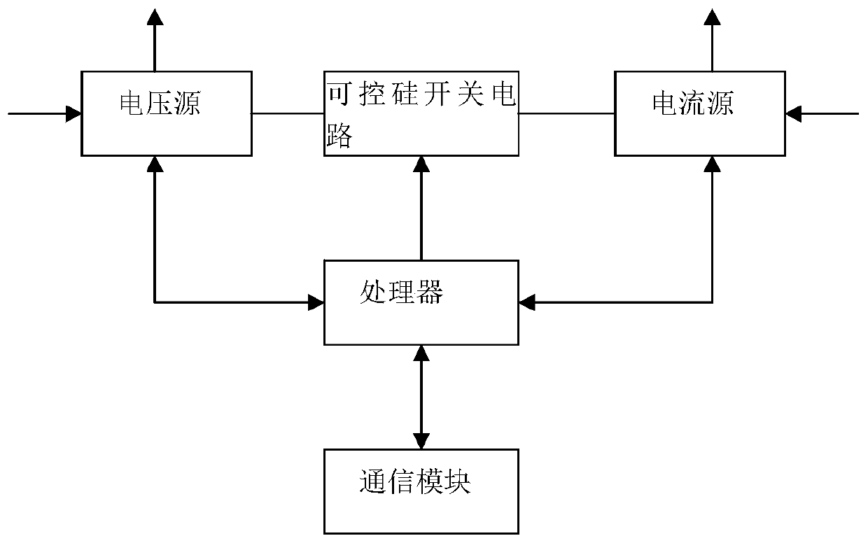
[0024] Embodiment 1: as figure 1 , image 3 , Figure 4 , image 3 , Figure 6 , Figure 7 , Figure 8 As shown, this embodiment provides a parallel high-power power supply, including one voltage source and one current source connected in parallel. The control terminals of the voltage source and the current source are connected to the processor at the same time, and receive control signals from the processor. Specifically, the voltage is derived from the processor receiving a reference DA voltage and outputting a specified voltage based on the reference DA voltage. The output ends of the voltage source and the current source are simultaneously connected to both ends of the thyristor switch circuit.

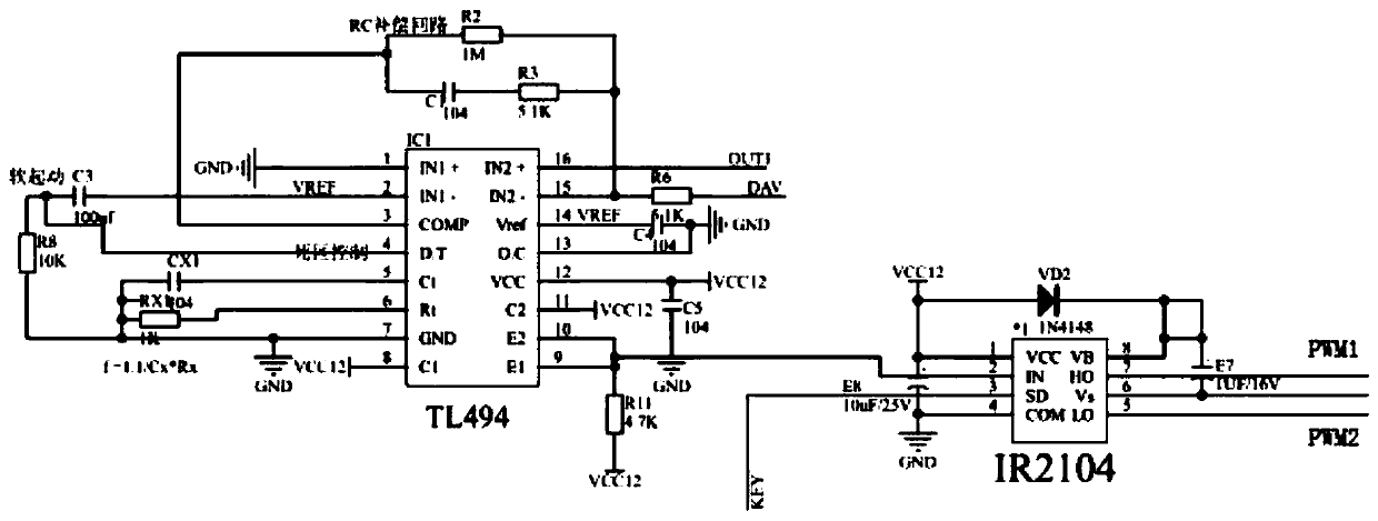
[0025] Such as image 3 , Figure 4 As shown, the voltage source adopts the BUCK synchronous step-down architecture, including a switching power supply controller, the switching power supply controller outputs PWM waves to the half-bridge driver according to the processor...

Embodiment 2

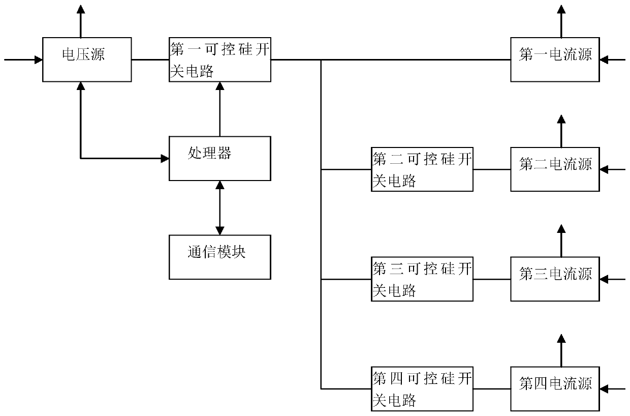
[0030] Embodiment 2: as figure 2 As shown, the difference from Embodiment 1 is that the parallel high-power power supply provided by this embodiment includes one voltage source connected in parallel and four current sources (the first current source, the second current source, the second Three current sources, the fourth current source), the control terminals of the voltage source and the four current sources are connected to the processor, and receive control signals from the processor. The voltage source is connected to the positive terminal of the one-way thyristor unit in the first thyristor switch circuit, and the output terminal of the first current source is connected to the negative terminal of the one-way thyristor unit in the first thyristor switch circuit; meanwhile, the first The second current source, the third current source, and the fourth current source pass through the second thyristor switch circuit, the third thyristor switch circuit, the fourth thyristor s...


PUM


Abstract

The invention relates to power-level direct-current power supply equipment, in particular to a parallel high-power power supply. The circuit comprises a voltage source and at least one current sourcewhich are connected in parallel. The control ends of the voltage source and the current source are connected with the processor at the same time and receive control signals from the processor. The output ends of the voltage source and the current source are simultaneously connected with the two ends of the silicon controlled rectifier switching circuit. By arranging the controllable voltage sourceand current source parallel circuit, a multi-stage parallel power supply mode is adopted when power is supplied to a load needing large-current power supply, and the output power of any one path canbe controlled at will. An independent output interface is reserved in each of the voltage source and the current source which are connected in parallel, and any voltage source and any current source are connected into the total output port by controlling the silicon controlled rectifier switching circuit to increase power output or the number of branches connected in parallel at the total output port is cut off to reduce power output when needed.

Description

technical field [0001] The invention relates to power-level DC power supply equipment, in particular to a parallel high-power power supply. Background technique [0002] At present, the low-voltage high-power power supplies on the market are generally isolated and forward-type power supplies. The output current provided by this type of power supply is usually between 50A and 100A. If the output current exceeds this range, the volume of the power supply will usually increase sharply. The increase in the size of the power supply means that more and larger heat dissipation equipment is required, which further causes the overall volume of the power supply to be bloated, which is not conducive to the user's carrying or outdoor use. [0003] In addition, when the power output of a single power supply is insufficient, at present, multiple power supplies are used in parallel to supply power. However, when multiple power supplies are used in parallel, various problems such as uncontr...

Claims


Application Information

Patent Timeline
Patent Type & Authority Applications(China)
IPC IPC(8): H02M3/158H02H7/12
CPCH02H7/1213H02M3/1584
Inventor 王海时杨森张兴涛齐佳玮文展陈昌明羊裔高文斌
Owner CHENGDU UNIV OF INFORMATION TECH
Why Eureka
Try Eureka