Realization circuit and realization method of constant current and constant power

A constant power and circuit technology, applied in the field of control circuits, can solve the problem that the shunt is difficult to meet the requirements of power derating, and achieve the effects of high accuracy, simple circuit structure and low cost.

Active Publication Date: 2014-06-18
SHENZHEN KSTAR SCI & TECH
View PDF6 Cites 12 Cited by
  • Summary
  • Abstract
  • Description
  • Claims
  • Application Information

AI Technical Summary

Problems solved by technology

If resistive components are used for current sampling, it will bring losses, such as shunts. Although the shunts are all milliohm level, in the case of high current output, the power consumption of the shunt will not be small. It is a few watts (W), so sometimes it is difficult for a shunt to meet its own power derating requirements, so the shu

Method used


Image

  • Realization circuit and realization method of constant current and constant power
  • Realization circuit and realization method of constant current and constant power
  • Realization circuit and realization method of constant current and constant power

Examples


Embodiment Construction

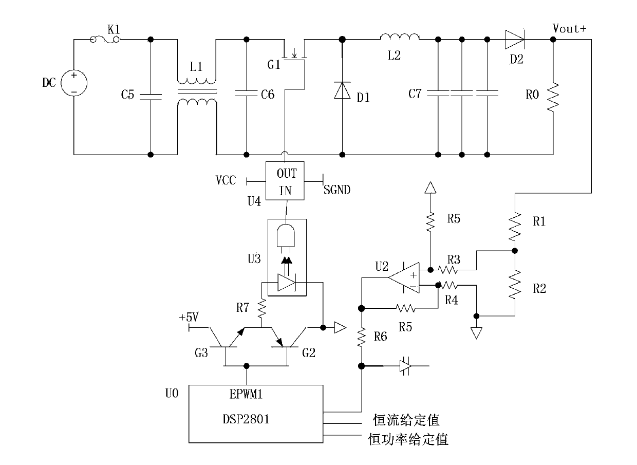
[0032] The invention realizes constant current and constant power output by sampling the voltage on the output resistor, and then utilizes chopping to realize constant current and constant power output without sampling components, and has many advantages such as easy implementation, simple circuit, and low implementation cost.

[0033] figure 2 Shown is a schematic circuit diagram of one embodiment of the present invention. The DC power supply reaches the output terminal through the main circuit to supply power for the resistive load R0 (also referred to as the load R0). By detecting the voltage across the resistive load R0 (that is, the output voltage), and then dividing it by the resistance value of the resistive load R0, that is The actual output current can be obtained, therefore, the output current sampling value is obtained by adopting the output current on the load R0; the current sampling circuit connected to the load R0 includes a voltage divider circuit connected to...


PUM


Abstract

The invention discloses a realization circuit and a realization method of a constant current and a constant power. The realization method comprises the following steps of: sampling an output current of a load R0 to acquire an output current sampling value; inputting the current sampling value, a constant current set value and a constant power set value to an A/D sampling port of a controller; when the constant value set value is greater than or less than the output current sampling value, sending a control signal by the controller so as to control a PWM drive chip to increase or decrease a duty cycle of a PWM signal output by the PWM drive chip, thereby realizing the constant current on the load R0; or calculating a power sampling value on the load R0 by using the output current sampling value, when the constant power set value is greater than or less than the power sampling value, sending a control signal by the controller to control the PWM drive chip to increase or decrease the duty cycle of the PWM signal output by the PWM drive chip, thereby realizing the constant power on the load R0. According to the realization circuit and the realization method of the constant current and the constant power disclosed by the invention, a current sampling element, such as a diverter, a Hall sensor or a mutual inductor, is not needed; moreover, the realization circuit and the realization method have the advantages of simple structure of the circuit, low realization cost, and the like.

Description

technical field [0001] The invention relates to a control circuit, in particular to a circuit and method for realizing constant current and constant power by using a simple resistance method. Background technique [0002] Generally, electronic loads will collect current in the design of constant current (CC mode) or constant power (CP mode) to realize the closed-loop control of constant current and constant power. [0003] Such as figure 1 Shown is a schematic circuit diagram of an existing electronic load realizing constant current or constant power. By adjusting the resistance of the variable resistor R2 to change the given input current, the comparator U1 compares the given input current with the current feedback collected from the shunt S1, and continuously adjusts the on-off time of the transistor G1 to change The duty cycle makes the current meet the given requirements, and the same principle is used to achieve constant current or constant power, except that a voltag...

Claims


Application Information

Patent Timeline
IPC IPC(8): G05F1/56
Inventor 王瑛董亚武
Owner SHENZHEN KSTAR SCI & TECH
Why Eureka
Try Eureka