Water conservancy irrigation device

An irrigation device and water conservancy technology, applied in the direction of watering devices, gardening, botanical equipment and methods, etc., can solve problems such as blockage and troublesome maintenance, and achieve the effect of reducing the number of pipelines and increasing the water consumption rate of irrigation

Active Publication Date: 2020-05-26
HEBEI RUNNONG WATER SAVING TECH
View PDF6 Cites 0 Cited by
  • Summary
  • Abstract
  • Description
  • Claims
  • Application Information

AI Technical Summary

Problems solved by technology

This technology can effectively improve the quality of agricultural products, but this method is easy to cause blockage, which adds trouble to later maintenance. Therefore, it is necessary to provide a method that does not hinder the planting and harvesting of crops and can also increase the irrigation water rate according to actual needs. water irrigation device

Method used


Image

  • Water conservancy irrigation device
  • Water conservancy irrigation device
  • Water conservancy irrigation device

Examples


Embodiment 1

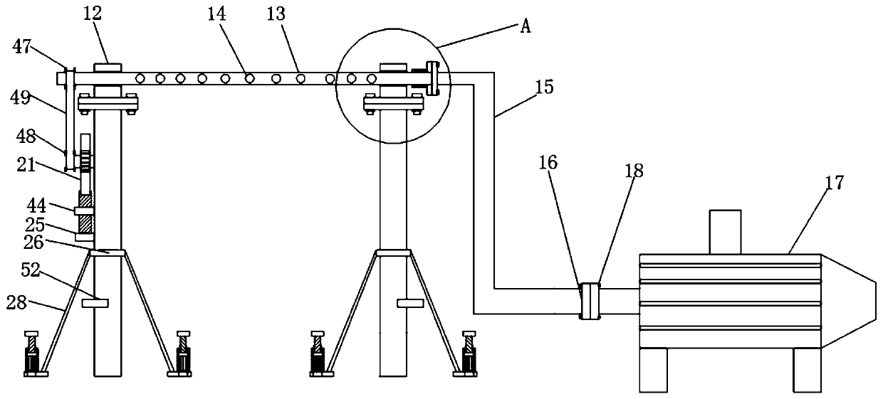
[0035] see Figure 1-10 , a water conservancy irrigation device according to an embodiment of the present invention, comprising two support columns 1, a cavity 2 is opened at the bottom of the support column 1, and a movable block 3 is arranged inside the cavity 2, The movable block one 3 is matched with the cavity 2, a limit mechanism is connected between the two sides of the movable block one 3 and the support column 1, and the bottom of the movable block one 3 is fixedly connected with a movable rod 4. The bottom of the movable rod 4 is fixedly connected with the movable block 2 5, the movable block 2 5 is matched with the cavity 2, the inner wall of the cavity 2 is fixedly connected with the limiting ring 6, and the limiting Ring 6 is positioned at the top of described movable block two 5, and limit ring 6 plays the effect of limit movable block one 3, makes movable block one 3 unable to break away from cavity 2 inside, and described limit ring 6 and described movable bloc...

Embodiment 2

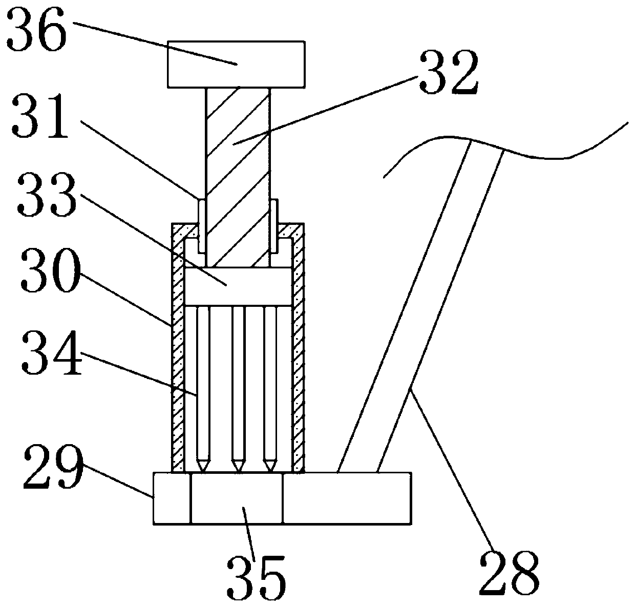
[0040] see image 3 , the insertion mechanism includes a sleeve 30, a threaded sleeve 31, a screw 32, a movable block three 33, an insertion rod 34 and a through hole 35, the top of the stable plate 29 is fixedly connected with a sleeve 30, and the sleeve 30 The top is fixedly connected with a threaded sleeve 31, and the internal thread of the threaded sleeve 31 is connected with a screw rod 32, and the bottom end of the screw rod 32 is positioned at the outside of the threaded sleeve 31 and is movably connected with the movable block three 33, and the screw rod 32 can pass through the bearing It is movably connected with the movable block three 33, and the bearing is embedded in the top of the movable block three 33, and the screw rod 32 is connected with the inner wall of the bearing. The movable block three 33 is matched with the inner wall of the sleeve 30, and the movable block three 33 The bottom is fixedly connected with a plurality of insertion rods 34. The bottom of t...

Embodiment 3

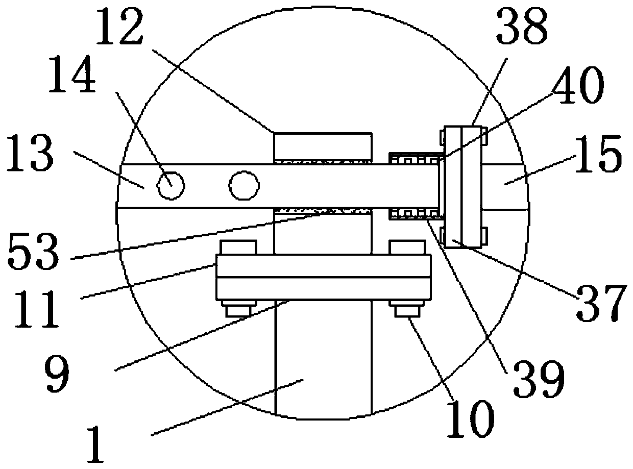
[0042] see figure 2 , the connecting mechanism includes a connecting flange one 37, a connecting flange two 38, a connecting sleeve 39 and a bearing one 40, the outer surface of one end of the movable pipe 13 close to the water pipe 15 is connected with a bearing one 40, and the bearing one The outer surface of 40 is fixedly connected with a connection sleeve 39, the port of the connection sleeve 39 is fixedly connected with a connection flange 1 37, and the end of the water pipe 15 close to the movable pipe 13 is connected with a connection flange 2 38, the connection The first flange 37 and the second connecting flange 38 are connected by bolts, and the connecting mechanism can connect the port of the movable pipe 13 to the water pipe 15 , and the rotation of the movable pipe 13 will not affect the water pipe 15 .


PUM


Abstract

The invention discloses a water conservancy irrigation device which includes two supporting columns. Supporting plates I are fixedly connected to the tops of the supporting columns, the supporting plates I are connected to supporting plates II through connecting bolts I, and fixed plates are fixedly connected to the tops of the supporting plate II; a movable tube is movably connected between the fixed plates, a plurality of water outlets are connected to the side wall of the movable tube, and one end of the movable tube is connected to a water tube through a connection mechanism; the end, awayfrom the movable tube, of the water tube is connected to a water pump; the end, away from the water tube, of the movable tube is connected to a movable shaft through a synchronization mechanism; themovable shaft is movably connected with the supporting columns, a gear is fixedly connected to the outer surface of the movable shaft, a tooth plate meshes one side of the gear, and a connecting blockI is fixedly connected to the side, away from the gear, of the tooth plate; and the bottom of the connecting block I is connected with a hydraulic telescopic rod. The water conservancy irrigation device has the beneficial effects that irrigation is carried out by spraying, and the irrigation water using rate is improved.

Description

technical field [0001] The invention relates to the technical field of irrigation, in particular to a water conservancy irrigation device. Background technique [0002] Irrigation, i.e. irrigating the land with water. The principle of irrigation is that the amount of irrigation, the frequency of irrigation and the time should be determined according to the water demand characteristics of medicinal plants, growth stages, climate, and soil conditions, and should be timely, appropriate, and rational irrigation. Its types mainly include pre-planting irrigation, seedling irrigation, growth period irrigation and winter irrigation, etc., which are technical measures to supplement the water required by crops. In order to ensure the normal growth of crops and obtain high and stable yields, crops must be supplied with sufficient water. Under natural conditions, often due to insufficient precipitation or uneven distribution, the water requirements of crops cannot be met. Therefore...

Claims


Application Information

Patent Timeline
Patent Type & Authority Applications(China)
IPC IPC(8): A01G25/02
CPCA01G25/02
Inventor 刘艳
Owner HEBEI RUNNONG WATER SAVING TECH
Why Eureka
Try Eureka