Electric hair drier

A hair dryer and fan technology, applied in the field of hair dryers, can solve the problems of air leakage, air volume and air pressure leakage, and air leakage, and achieve the effects of reducing air volume, reducing air volume and air pressure loss, and simplifying the structure.

Pending Publication Date: 2020-05-26
LESHOW ELECTRONICS TECH CO LTD
View PDF0 Cites 2 Cited by
  • Summary
  • Abstract
  • Description
  • Claims
  • Application Information

AI Technical Summary

Problems solved by technology

[0002] The existing hair dryer that takes in air from the handle assembly includes a casing connected to the handle assembly, the fan unit is arranged in the handle assembly, and the handle assembly is provided with an air inlet. The installation of the structural parts in the handle assembly divides the handle assembly into multiple parts, and there will be assembly gaps when the parts are assembled together, causing airflow to leak out; moreover, the handle assembly is equipped with electronic devices, such as switches. For the convenience of users, the switch It is installed above the fan unit, and the switch needs to be opened on the handle assembly, and the airflow will leak from the switch, resulting in leakage of air volume and air pressure, and the setting of the sealing structure will increase the complexity of assembly

Method used


Image

  • Electric hair drier
  • Electric hair drier
  • Electric hair drier

Examples


Embodiment 1

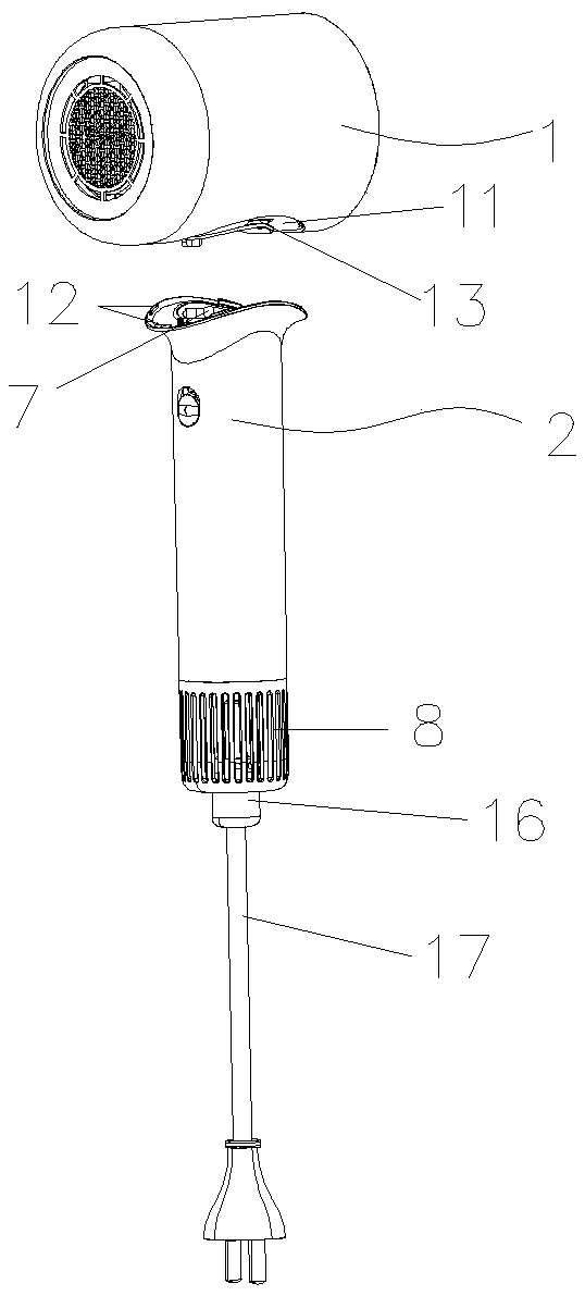
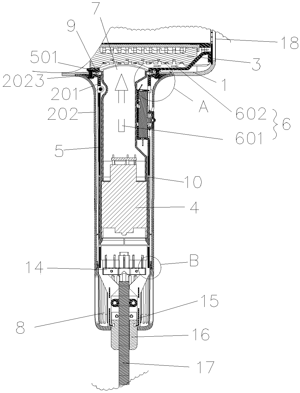
[0040] Such as Figures 1 to 9 As shown, a hair dryer includes a housing 1 and a handle assembly 2 connected to the housing 1, extending from the air inlet 8 of the hair dryer to the main air duct 6 of the air outlet 18, and is arranged in the main air duct 6 for suction The airflow enters the fan unit 4 of the hair dryer from the air inlet 8 and the heating unit 3 for heating the airflow. The fan unit 4 includes a fan blade 403 and a motor 401 for driving the fan blade 403 to rotate, wherein the fan unit 4 is disposed in the handle assembly 2, the air inlet 8 is disposed on the handle assembly 2, and the handle assembly 2 is also provided with an air guide pipe 5 for conveying the airflow of the main air duct 6. The air guide pipe 5 may define a part of the main air duct 6 or may define the entire main air duct 6 . The air guide pipe 5 is preferably made of soft rubber, such as silica gel.

[0041] Further, such as figure 2 As shown, the main air duct 6 includes a vertica...

Embodiment 2

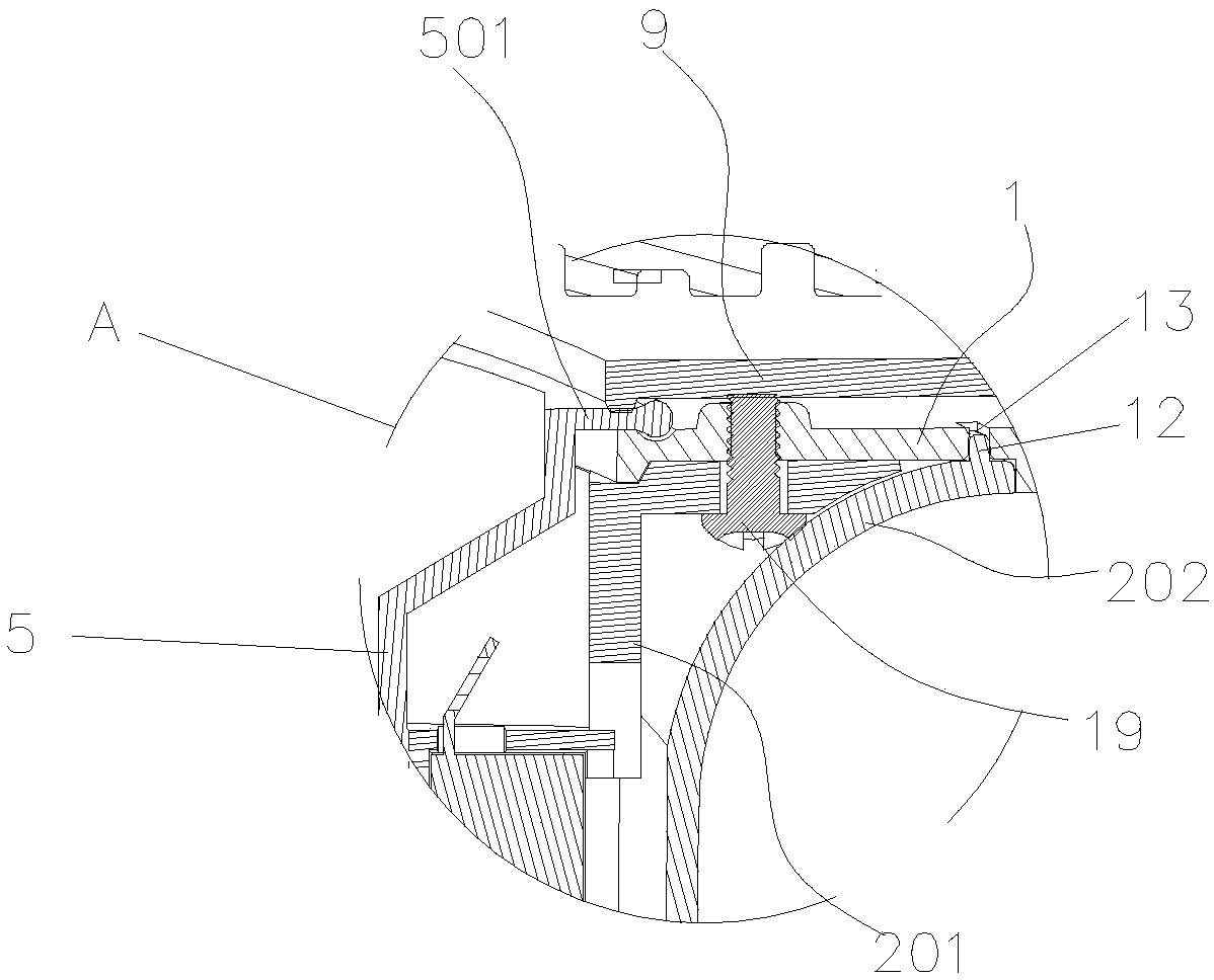
[0056] The difference between Embodiment 2 and Embodiment 1 is that, as Figures 9 to 11 As shown, the fixing bracket 201 also includes a second part 2012 extending along its axis direction, the fan unit 4 is disposed in the opening 2014, the second part 2012 is connected with the first part 2011 to cover the opening 2014 to Fix the fan unit 4; in this example, put the air duct 5 on the fan unit 4, put it into the first part 2011, fasten the second part 2012 with the first part 2011, and put the outer handle 202 on it That is; further, the two halves of the fixing bracket 201 can be connected by screws 19, that is, the first part 2011 and the second part 2012 are connected together by screws 19, so as to achieve fixing reliability. The card slot 10 can be provided only on the first part 2011, or can be provided on the second part 2012 at the same time, so as to make the fixing more reliable and reduce vibration and noise.

[0057] In addition, in order to further ensure the c...

Embodiment 3

[0059] The difference between the third embodiment and the first embodiment is that the first outer handle 2021 and the fixed bracket 201 are connected by screws 19 at the lower end, furthermore, the first outer handle 2021 and the first part 2011 between the fixed part 201 are connected by screws 19 at the lower end connect.


PUM


Abstract

The invention relates to the field of household appliances; for the fact that air flow is conveyed into a shell from a handle assembly, and air pressure and air volume losses are reduced as much as possible, the invention relates to an electric hair drier comprising a shell, a handle assembly connected with the shell, a main air duct extending from an air inlet of the electric hair drier to an airoutlet, a fan unit arranged in the main air duct and used for sucking air flow into the electric hair drier from the air inlet, and a heating unit used for heating the air flow; the fan unit comprises fan blades and a motor used for driving the fan blades to rotate, the fan unit is arranged in the handle assembly, the air inlet is formed in the handle assembly, and an air guide pipe used for conveying the air flow of the main air duct is further arranged in the handle assembly. Air volume and air pressure losses are reduced.

Description

technical field [0001] The invention relates to the field of household appliances, in particular to a hair dryer. Background technique [0002] The existing hair dryer that takes in air from the handle assembly includes a casing connected to the handle assembly, the fan unit is arranged in the handle assembly, and the handle assembly is provided with an air inlet. The installation of the structural parts in the handle assembly divides the handle assembly into multiple parts, and there will be assembly gaps when the parts are assembled together, causing airflow to leak out; moreover, the handle assembly is equipped with electronic devices, such as switches. For the convenience of users, the switch If it is installed above the fan unit, the switch needs to have a hole in the handle assembly, and the airflow will leak from the switch, resulting in leakage of air volume and air pressure, and the setting of the sealing structure will increase the complexity of assembly. [0003]...

Claims


Application Information

Patent Timeline
Patent Type & Authority Applications(China)
IPC IPC(8): A45D20/10A45D20/12
CPCA45D20/10A45D20/12
Inventor 喻金明叶志文肖林
Owner LESHOW ELECTRONICS TECH CO LTD
Why Eureka
Try Eureka