Gas-liquid vibration damping device

A damping device, gas-liquid technology, applied in gas-liquid shock absorbers, shock absorbers, shock absorbers, etc., can solve the problem of low boiling point of damping oil in hydraulic shock absorbers, affecting the service life of shock absorbers, and airtightness High performance requirements and other issues, to achieve the effect of low cylinder wall strength requirements, avoid severe vibration, and increase control stability

Pending Publication Date: 2018-02-27
GUILIN UNIV OF ELECTRONIC TECH
View PDF11 Cites 5 Cited by
  • Summary
  • Abstract
  • Description
  • Claims
  • Application Information

AI Technical Summary

Problems solved by technology

[0004] When the hydraulic shock absorber is working, the oil agitation resistance can buffer the impact force of the piston rod, but at the same time it will also generate a lot of heat, which seriously affects the service life of the shock absorber and has relatively high requirements for air tightness, which is prone to leakage. oil phenomenon
[0005] Pneumatic shock absorbers have a simple structure and are cheaper than hydraulic shock absorbers. The gas flow inside and outside the shock absorber is mainly realized through double-pass loops, but the shock absorption stability is not as good as that of hydraulic shock absorbers. The air pressure is unstable, and the temperature is too high, which affects the original accuracy
[0006] The hydraulic shock absorber has a low boiling point of damping oil and is more comfortable than pneumatic shock absorbers, but it is not suitable for long-distance driving and has high requirements for rigid body sealing

Method used


Image

  • Gas-liquid vibration damping device

Examples


Embodiment Construction

[0022] The technical solutions of the present invention will be further described below in conjunction with the embodiments shown in the accompanying drawings.

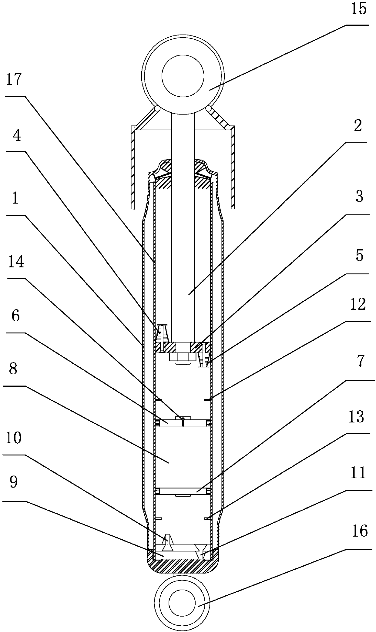
[0023] The gas-liquid vibration damping device of the present invention has a structure comprising a coaxial outer oil storage cylinder 1 and an inner oil storage cylinder 17, a piston rod 2 and a hydraulic piston 3, and the lower end of the oil cylinder rod 2 is connected to the inner oil storage cylinder 17. The oil pressure piston 3 and the upper end of the oil cylinder rod 2 are connected to the upper support 15 outside the inner and outer oil storage cylinders 17 and 1, and the oil pressure piston 3 divides the inner cavity of the inner oil storage cylinder 17 into an upper pressure chamber and a lower pressure chamber , the hydraulic piston 3 is provided with an expansion valve 4 and a compression valve 5; the lower pressure chamber includes an upper oil chamber, a floating air pressure chamber in the middle and ...


PUM


Abstract

The invention discloses a gas-liquid vibration damping device. The gas-liquid vibration damping device comprises an inner oil storage cylinder, an outer oil storage cylinder, a piston rod and an oil hydraulic piston. An inner cavity of the inner oil storage cylinder is divided into an upper pressure cavity and a lower pressure cavity through the oil hydraulic piston. A partition plate of a lower cylinder opening of the inner oil storage cylinder is provided with a compensating valve and a circulating valve, wherein the compensating valve guides hydraulic oil between the inner oil storage cylinder and the outer oil storage cylinder into the lower pressure cavity, and the circulating valve guides hydraulic oil in the lower pressure cavity into the position between the inner oil storage cylinder and the outer oil storage cylinder. The oil hydraulic piston is connected to the position, in the inner oil storage cylinder, of the lower end of the piston rod. The oil hydraulic piston is provided with a compression valve and an extension valve, wherein the compression valve guides the hydraulic oil in the lower pressure cavity into the upper pressure cavity, and the extension valve guides hydraulic oil in the upper pressure cavity into the lower pressure cavity. The lower pressure cavity is internally provided with an upper air pressure piston and a lower air pressure piston and is divided into an upper oil cavity, a middle floating air pressure chamber and a lower oil cavity. According to the gas-liquid vibration damping device, the floating air pressure chamber is arranged additionally on the basis of a traditional double-barrel-type hydraulic damper, and impact exerted on the oil hydraulic piston can be effectively relieved.

Description

technical field [0001] The invention relates to auto parts, in particular to a gas-liquid damping device. Background technique [0002] The shock absorber and spring of the automobile suspension can buffer the vibration of the car body caused by the impact of pulse excitation and random excitation on the road surface. The shock absorber mainly suppresses the rebound vibration of the spring after being impacted and the impact from the road surface. [0003] The types of automobile shock absorbers include hydraulic shock absorbers, pneumatic shock absorbers, and compound cylinder shock absorbers. [0004] When the hydraulic shock absorber is working, the oil agitation resistance can buffer the impact force of the piston rod, but at the same time it will also generate a lot of heat, which seriously affects the service life of the shock absorber and has relatively high requirements for air tightness, which is prone to leakage. oil phenomenon. [0005] Pneumatic shock absorbers...

Claims


Application Information

Patent Timeline
Patent Type & Authority Applications(China)
IPC IPC(8): F16F9/06F16F9/32B60G13/06
CPCF16F9/062F16F9/067F16F9/3242B60G13/06
Inventor 何水龙汤涛韦壹王衍学叶明松蒋占四唐荣江
Owner GUILIN UNIV OF ELECTRONIC TECH
Why Eureka
Try Eureka