Continuous dust removal device for communication base station

A technology for communication base stations and dust removal devices, which is used in transportation and packaging, dispersed particle separation, chemical instruments and methods, etc., can solve problems such as large operational uncertainty, high manual operation work intensity, and inability to guarantee the quality of dust removal.

Inactive Publication Date: 2020-05-26
钱丰
View PDF0 Cites 7 Cited by
  • Summary
  • Abstract
  • Description
  • Claims
  • Application Information

AI Technical Summary

Problems solved by technology

[0003] At present, most of the communication base stations are built in remote areas far away from towns and cities, and no one is guarding them. The filter screen inside the dust removal device of the prior art needs to be cleaned manually after a period of use to ensure that it can remove dust smoothly. The work intensity of manual operation is high, and it is considered that the operation uncertainty is relatively large, and the quality of dust removal cannot be guaranteed. Therefore, it is necessary to install a continuous dust removal device for communication base stations to solve the above technical problems.

Method used


Image

  • Continuous dust removal device for communication base station
  • Continuous dust removal device for communication base station
  • Continuous dust removal device for communication base station

Examples


Embodiment 1

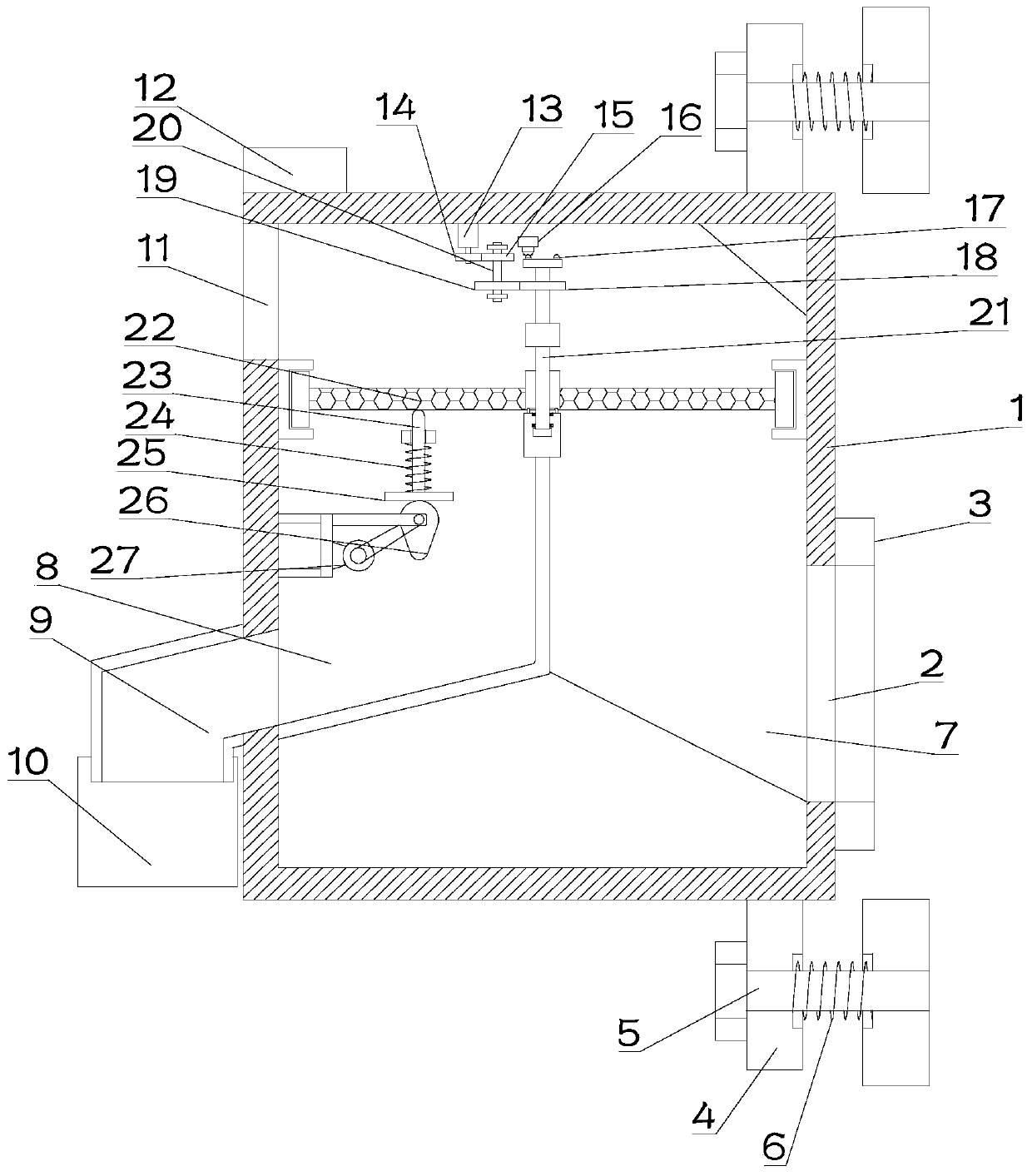
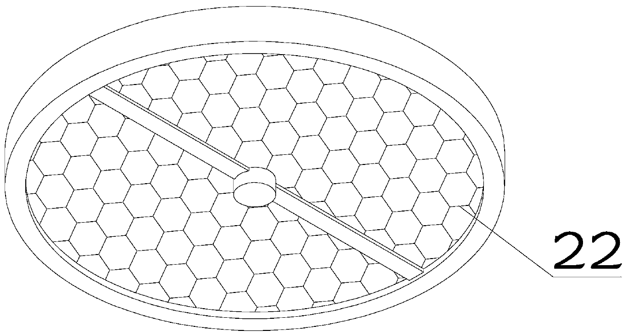
[0023] see Figure 1~3 , in Embodiment 1 of the present invention, a continuous dust removal device for a communication base station includes a dust removal main body 1, and a cavity is arranged inside the dust removal main body 1, and the cavity is divided into a filter chamber 7 and a cleaning chamber 8 by a partition , the filter cavity 7 is used to filter the air, and the cleaning cavity 8 is used to clean the dust on the filter screen; one side of the filter cavity 7 is provided with an air inlet 2, and the filter cavity 7 and the upper end of the cleaning cavity 8 are A filter screen 22 is rotated at the communication port, and an exhaust port 11 is also provided on the dust removal main body 1. The air inlet 2 and the exhaust port 11 are respectively arranged on the upper and lower parts of the filter screen 22. The filter screen 22 It is a circular structure, and is evenly divided into two parts; the inside of the cleaning chamber 8 is provided with a vibrating mechani...

Embodiment 2

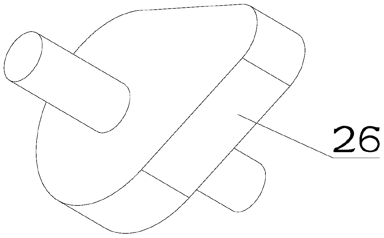
[0025] see Figure 1~3 The main difference between this embodiment 2 and embodiment 1 is that the vibrating mechanism includes a vibrating rod 23, the upper end of the vibrating rod 23 is in contact with the bottom of the filter screen 22, and the vibrating rod 23 is set through the through hole on the support block, And the driving block 25 is installed on the bottom of the vibrating rod 23, the outer side of the vibrating rod 23 is sleeved with a B elastic member 24, and the upper and lower ends of the B elastic member 24 are fixedly installed on the supporting block and the driving block 25 respectively, and the supporting block Fixedly installed inside the cleaning chamber 8, the bottom of the drive block 25 is in contact with a cam 26 that drives the drive block 25 to reciprocate up and down, and the cam 26 is fixed inside the cleaning chamber 8 through a bracket, and the cam 26 drives the drive block 25 to drive the vibration The rod 23 reciprocates up and down, and then...


PUM


Abstract

The invention discloses a continuous dust removal device for a communication base station, which relates to the technical field of communication equipment. The device comprises a dust removal body, and a cavity is formed in the dust removal body and is divided into a filtering cavity and a cleaning cavity through a partition plate; an air inlet is formed in one side of the filter cavity, a filterscreen is rotationally arranged at a communicating opening in the upper ends of the filtering cavity and the cleaning cavity, an exhaust port is further formed in the dust removal body, the air inletand the exhaust port are formed in the upper portion and the lower portion of the filtering screen respectively, and the filtering screen is of a circular structure and is equally divided into two parts, a vibrating mechanism for driving the filtering screen part arranged at the communicating opening in the upper end of the cleaning cavity to vibrate up and down is arranged in the cleaning cavity,the middle of the filtering screen is fixedly mounted on a rotating shaft, the rotating shaft is rotationally mounted in the dust removal body, and an intermittent rotating mechanism for driving therotating shaft to drive the filtering screen to rotate is arranged in the dust removal body. Air is continuously filtered, and a filtering screen can be prevented from being manually and regularly cleaned.

Description

technical field [0001] The invention relates to the technical field of communication equipment, in particular to a continuous dust removal device for a communication base station. Background technique [0002] The internal space of the communication base station computer room is compact and relatively closed. The continuous operation of the equipment in the computer room has a high heat dissipation, and the temperature rise often causes the communication equipment in the computer room to work abnormally or even be damaged. In order to ensure the normal operation of the base station equipment, ventilation equipment must be provided. The equipment inside the base station is more afraid of dust in this application, and if there is a lot of dust inside, it will affect the life of the equipment. Therefore, it is necessary to install a dust removal device on the ventilation equipment. [0003] At present, most of the communication base stations are built in remote areas far away...

Claims


Application Information

Patent Timeline
Patent Type & Authority Applications(China)
IPC IPC(8): B01D46/00B01D46/10B01D46/48B01D46/42
CPCB01D46/10B01D46/48B01D46/4236B01D46/90B01D46/76
Inventor 钱丰
Owner 钱丰
Why Eureka
Try Eureka