Self-cleaning revolving door

A revolving door and self-cleaning technology, which is applied in the field of revolving doors, can solve the problems that the revolving door cannot stop running during the day, the operation is inconvenient, and the aesthetics of the revolving door is affected.

Inactive Publication Date: 2020-05-26
姚宏应
View PDF7 Cites 14 Cited by
  • Summary
  • Abstract
  • Description
  • Claims
  • Application Information

AI Technical Summary

Problems solved by technology

[0003] When there is a large flow of people in a large shopping mall or office building, the people coming and going will carry a lot of dust, which makes the dust easily adhere to the glass of the revolving door, which affects the aesthetics of the revolving door. In order to ensure the ...

Method used


Image

  • Self-cleaning revolving door
  • Self-cleaning revolving door
  • Self-cleaning revolving door

Examples


Embodiment 1

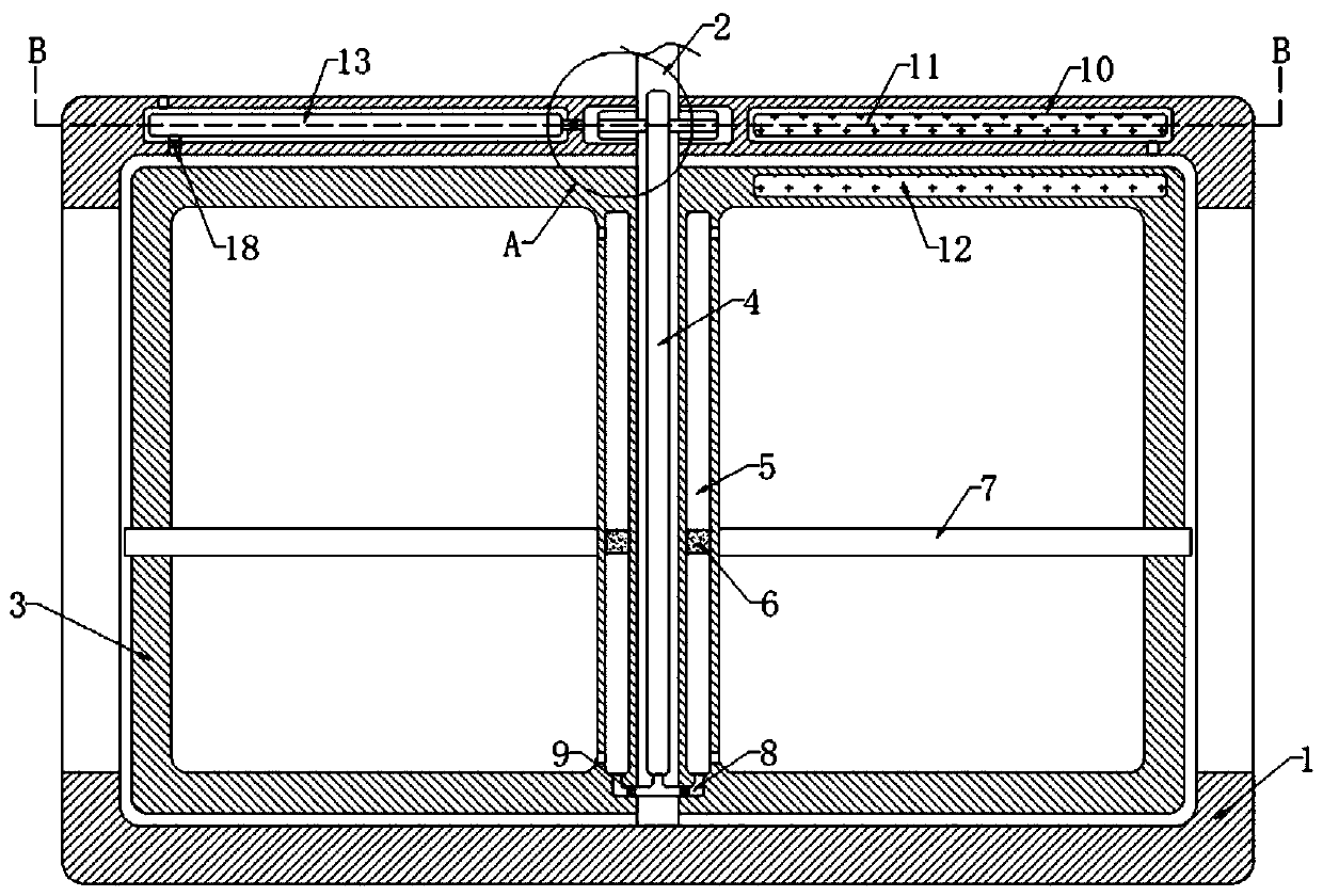
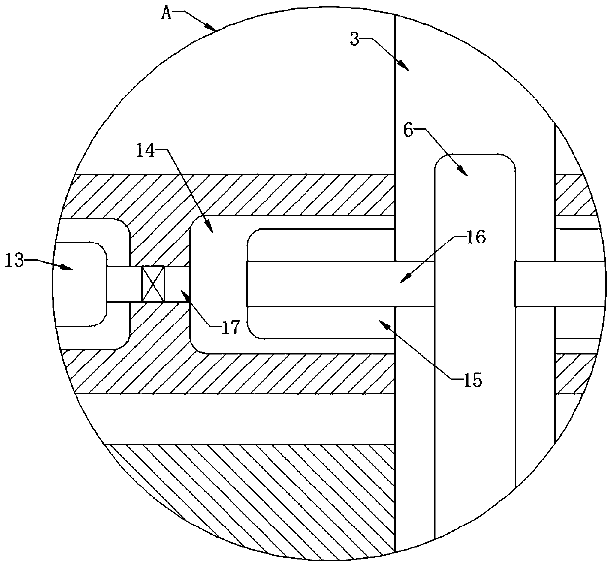
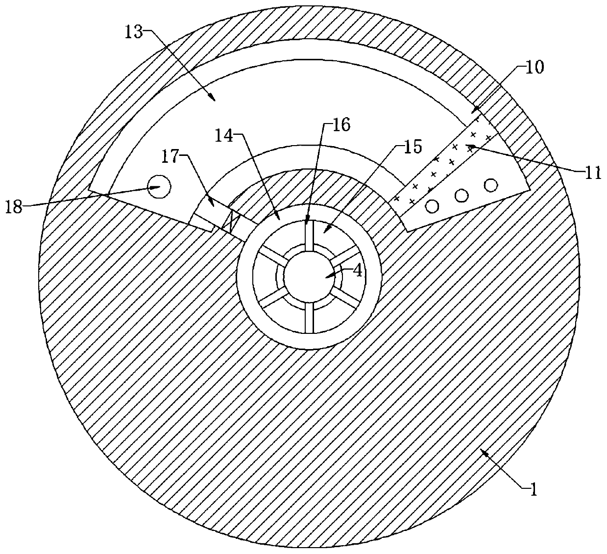
[0024] refer to Figure 1-3 , a self-cleaning revolving door, comprising a cylindrical door frame 1, the inner wall of the cylindrical door frame 1 is rotatably connected with a rotating shaft 2, and the rotating shaft 2 is driven by an external drive motor, which is the prior art, and the side walls of the rotating shaft 2 are evenly distributed and fixedly connected to a plurality of Revolving door frame 3, the inner wall of cylindrical door frame 1 and revolving door frame 3 is fixedly connected with glass, the inner wall of rotating shaft 2 is provided with cavity 4, and the side wall of revolving door frame 3 close to rotating shaft 2 is provided with sliding plug chamber 5, the inner wall of sliding plug chamber 5 is below A small hole communicating with the outside world is provided, and the inner wall of the sliding plug chamber 5 is slidably connected with a magnetic sliding plug 6. Further, a through hole communicating with the outside world is provided above the inne...

Embodiment 2

[0031] refer to Figure 4 The difference from Embodiment 1 is that a water storage chamber 19 is provided on the side wall of the revolving door frame 3 away from the rotating shaft 2, and the inner bottom of the water storage chamber 19 is elastically connected with a slide plate 20 through a spring 21. Further, the inner wall of the water storage chamber 19 is connected with a The water inlet pipe is convenient to add cleaning liquid to the water storage chamber 19. Further, when the water in the water storage chamber 19 is used every time, the spring 21 can push the slide plate 20 to move upward, so that the water contacts the top of the liquid storage chamber 18 , and at this time the spring 21 and the water are kept in a balanced state, so that when gas enters, the water can be squeezed out at the first time, the inner bottom of the water storage chamber 19 communicates with the air outlet chamber 8 through the air inlet chamber 22, and the door frame 3 is rotated The upp...


PUM


Abstract

The invention discloses a self-cleaning revolving door. The self-cleaning revolving door comprises a cylindrical door frame, wherein a rotating shaft is rotatably connected to the inner wall of the cylindrical door frame, a plurality of rotating door frames are fixedly connected to the side wall of the rotating shaft in an uniformly distributed mode, sliding plug cavities are formed in the side wall, close to the rotating shaft, of the rotating door frames, magnetic sliding plugs are slidably connected to the inner walls of the sliding plug cavities, and cleaning strips attracted to the magnetic sliding plugs are slidably connected to the side walls of the rotating door frames. The non-stop rotation of the rotating door frames causes the iron sliding blocks to intermittently compress telescopic air bags, gas in the telescopic airbags enters a cavity for storage, when the pressure intensity in the cavity reaches a threshold value of a pressure relief valve, the pressure relief valve isopened, so that the gas in the cavity enters the sliding plug cavities through an air inlet cavity, the magnetic sliding plugs are pushed to slide upwards, the cleaning strips are driven to move upwards on the side walls of the rotating door frames, glasses on the rotating door frames are self-cleaned, and the problem of too much dust on the glasses that affects the aesthetics of the revolving door is avoided.

Description

technical field [0001] The invention relates to the technical field of revolving doors, in particular to a self-cleaning revolving door. Background technique [0002] Because the revolving door integrates the advantages of various door bodies, its spacious and high-style design creates a luxurious atmosphere, which can be called the finishing touch of a building, making the revolving door mostly used in large shopping malls or office buildings. [0003] When there is a large flow of people in a large shopping mall or office building, the people coming and going will carry a lot of dust, which makes the dust easily adhere to the glass of the revolving door, which affects the aesthetics of the revolving door. In order to ensure the indoor and outdoor Unobstructed, the revolving door cannot stop running during the day, and then it cannot be cleaned frequently. In addition, because the revolving door body is high, cleaning personnel need to use climbing tools to clean it, which ...

Claims


Application Information

Patent Timeline
IPC IPC(8): E06B3/90E06B7/28A47L1/02
CPCA47L1/02E06B3/90E06B7/28
Inventor 姚宏应
Owner 姚宏应
Why Eureka
Try Eureka