Flow guide plate of fuel cell

A fuel cell and deflector technology, applied in fuel cells, fuel cell parts, circuits, etc., can solve the problems of air waste, increased mechanical power consumption of transporting air or circulating hydrogen, and reducing the efficiency of fuel cell systems, etc., to achieve Improve delivery

Active Publication Date: 2020-05-26
氢鑫沃德(上海)新能源发展有限公司
View PDF11 Cites 11 Cited by
  • Summary
  • Abstract
  • Description
  • Claims
  • Application Information

AI Technical Summary

Problems solved by technology

[0005] This design is to design more fluid inlets and outlets, and design the diversion groove as a straight-flow groove or a near-flow groove as much as possible. Compared with the traditional serpentine flow path, it does reduce the situation of water blocking. Due to the limitation of the size of the flow plate, the design of this straight channel makes hydrogen and air be discharged from the stack before they can react, a large amount of air is wasted or excess hydrogen is circulated, which will inevitably cause the mechanical work of transporting air or circulating hydrogen. consumption increases, thereby reducing the efficiency of the fuel cell system

Method used


Image

  • Flow guide plate of fuel cell
  • Flow guide plate of fuel cell
  • Flow guide plate of fuel cell

Examples


Embodiment 1

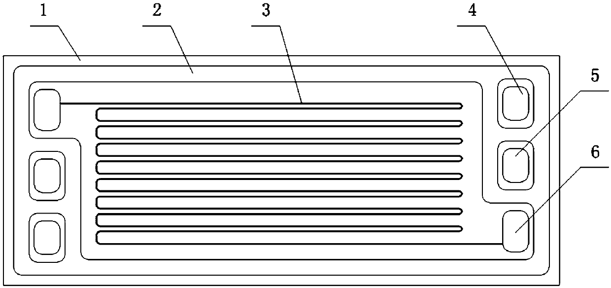
[0040] Such as figure 1 As shown, it is a structural schematic diagram of a conventional direct-flow deflector. The deflector 1 is provided with a linear fluid channel 3, and the two ends of the deflector 1 are provided with a fuel inlet and outlet 4, a cooling fluid inlet and outlet 5, and an oxidant inlet and outlet. 6. A sealing groove 2 is also provided.

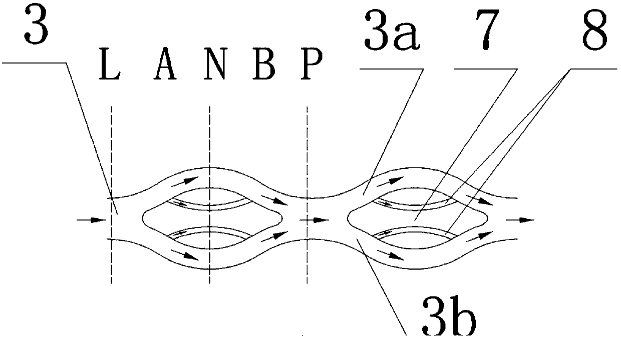
[0041] The present invention changes fluid channel 3 into such as figure 2 In the shown structure, a plurality of flow-distributing islands 7 are arranged in the middle of each fluid channel 3, so that the fluid channel is divided into two when passing through the flow-distributing islands 7 (such as Figure 2-5 As shown, when the fluid passage 3 is in the L cross section, it is divided into two paths: the shunt passage 3a and the shunt passage 3b), and after passing through the shunt island 7, they are merged into one at the P cross section to form a wave-like fluid passage that continuously expands and converges . ...

Embodiment 2

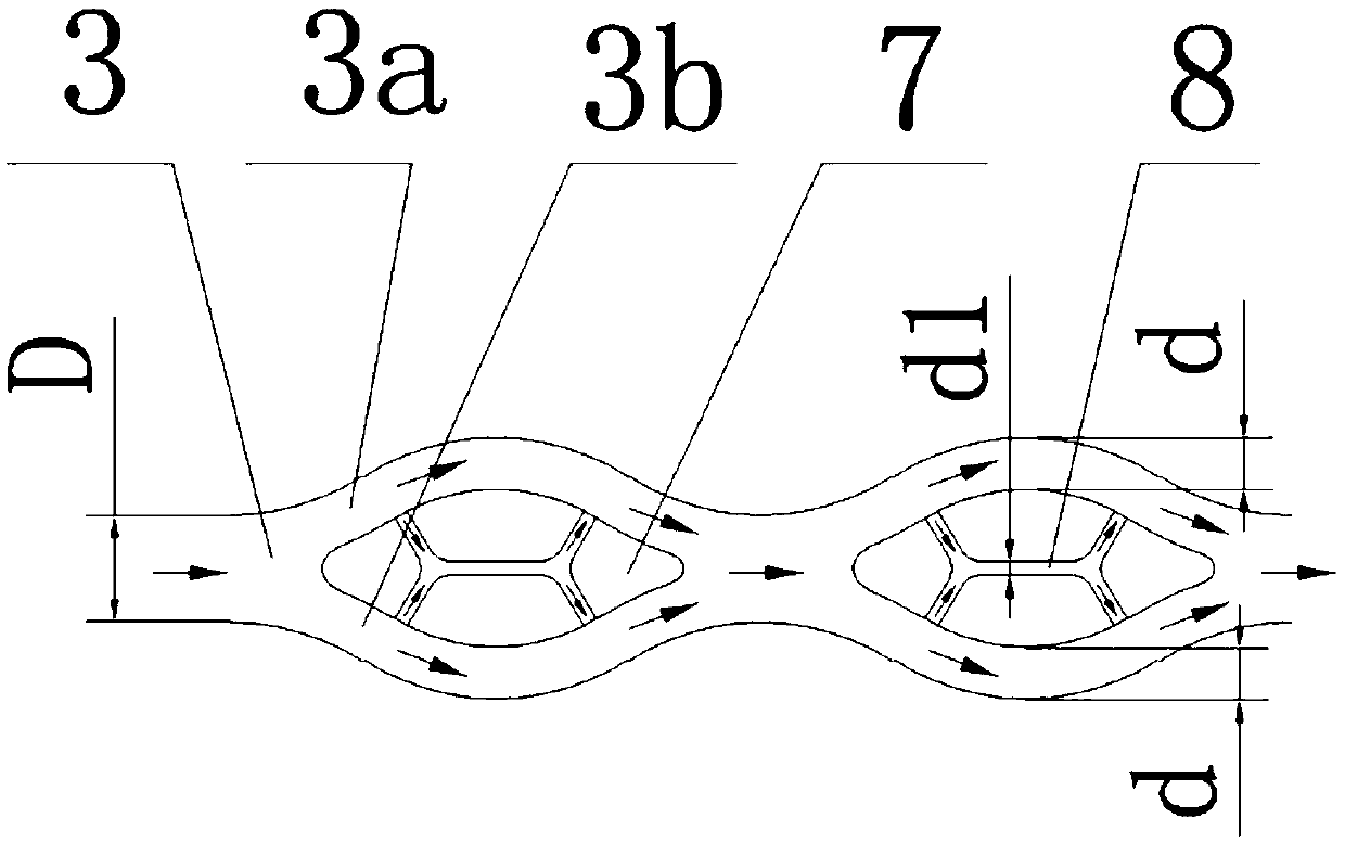
[0049] A plurality of diversion islands 7 are arranged in the middle of each fluid channel 3, so that the fluid channel is divided into three flow channels when passing through each diversion island 7, and after passing through the diversion island 7, there is a joint to form a wave-like expansion and convergence fluid channel. All the other are with embodiment 1.


PUM


Abstract

The invention relates to a flow guide plate of a fuel cell. The flow guide plate (1) is provided with a plurality of fluid channels (3); the single fluid channel is branched, diffused and converged, the width and depth of each section of the same fluid channel are changed, the flow velocity and pressure of the fluid are adjusted, the flowing quality is improved, the fluid is forced to flow along the fluid channel at a variable speed, and meanwhile, the fluid can enter a diffusion layer to form three-dimensional multi-layer flowing. Compared with the prior art, by changing the flow velocity andpressure of the fluid at each position point in the fluid channel, a reaction medium can be transferred more effectively, the generated water can be discharged more effectively, and the method has the advantages of improving the performance of a stack, improving the reaction efficiency, prolonging the service life of the stack and the like.

Description

technical field [0001] The invention relates to a fuel cell, in particular to a fuel cell deflector. Background technique [0002] A fuel cell is a device that directly converts the chemical energy of hydrogen and oxygen into electrical energy through an electrode reaction. A fuel cell is generally constructed of a plurality of cells, each cell comprising two electrodes (anode and cathode) separated by an electrolyte element and assembled in series with each other to form a fuel cell stack. The electrochemical reaction is achieved by supplying the appropriate reactants to each electrode, ie fuel to one electrode and oxidant to the other, creating a potential difference between the electrodes and thereby generating electrical energy. [0003] In order to supply each electrode with reactants, specific interface elements commonly referred to as "bipolar plates" and arranged on both sides of each individual cell are used. These bipolar plates are usually in the form of a singl...

Claims


Application Information

Patent Timeline
Patent Type & Authority Applications(China)
IPC IPC(8): H01M8/0258H01M8/026
CPCH01M8/0258H01M8/026H01M8/0263H01M8/0267Y02E60/50H01M8/0228H01M8/04156H01M8/0265
Inventor 高勇
Owner 氢鑫沃德(上海)新能源发展有限公司
Why Eureka
Try Eureka