
Fluid agitating device equipped with such an agitating device

一种设备、流体的技术,应用在具有旋转搅拌装置的混合机、混合机、溶解等方向,能够解决效率低下等问题

Active Publication Date: 2020-05-26
FILLON PICHON SOCIETE ANONYME
View PDF8 Cites 2 Cited by
  • Summary
  • Abstract
  • Description
  • Claims
  • Application Information

AI Technical Summary

Problems solved by technology

These mixing devices are ineffective at mixing product that has accumulated a portion of it by settling in the bottom of the container

Method used


Image

  • Fluid agitating device equipped with such an agitating device
  • Fluid agitating device equipped with such an agitating device
  • Fluid agitating device equipped with such an agitating device

Examples


Embodiment Construction

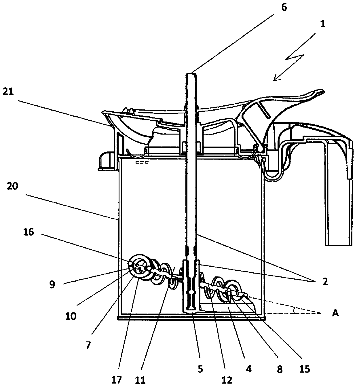
[0033] As already mentioned above, the subject of the present invention is a device 1 for stirring fluids, in particular liquids, especially suitable for stirring paint stored in a container 20, such as a tank, closed by a lid 21, The stirring device 1 protrudes at least partially from the cover 21 .

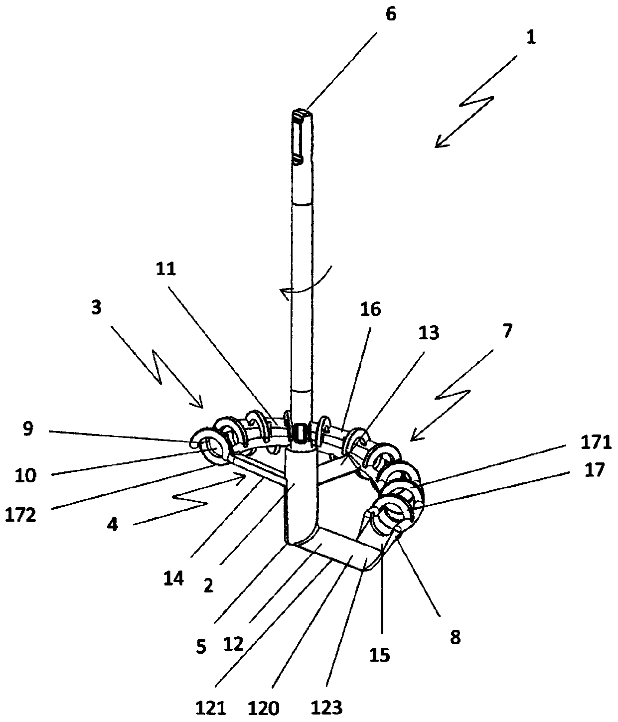
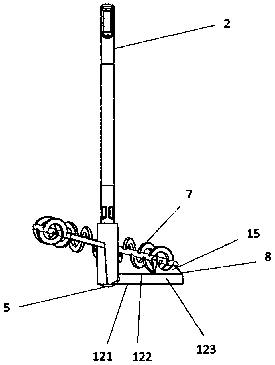
[0034] The stirring device 1 comprises: a stirring shaft 2, which can be driven in rotation, in particular rotating on itself; a stirring element 3; and means 4 for connecting between the stirring element 3 and the stirring shaft 2, in the configuration of use The stirring shaft 2 can be positioned vertically from its lower end 5 in the direction of its upper end 6 (ie substantially perpendicular to the face forming the bottom of the container 20).

[0035] The stirring shaft 2 can be driven to rotate in various ways depending on the environment in which the stirring device 1 is arranged. Thus, the stirring shaft 2 can be coupled to a drive head equipped on the stirring chamber...


PUM


Abstract

The invention relates to an agitating device (1) comprising a stirring shaft (2) that is vertically positionable in a use configuration, a stirring element comprising a circular ring portion (7) partially surrounding the agitating shaft (2), this ring portion, in the use configuration of the shaft (2), being disposed in a plane that is inclined with respect to the shaft (2) and develops around theshaft (2) from the lower end (8) thereof in the direction of the upper end (9) thereof, following an ascending slope, this ring portion (7) being hollow and provided with openings (11) for communicating with the outside and means (4) for connecting the stirring element and the shaft (2). These connecting means (4) comprise at least one arm (12) that is radial to the agitating shaft (2) and connects the lower end (5) of the agitating shaft (2) and the lower end (8) of the stirring element, and extends at least partially in a plane perpendicular to the agitating shaft (2).

Description

technical field [0001] The present invention relates to a device for agitating a fluid, such as paint, contained in a container such as a tank, and also to a cover for a container equipped with such a stirring device. [0002] More specifically, the invention relates to an apparatus for stirring a fluid comprising a rotationally drivable stirring shaft, a stirring element and means for connecting between the stirring element and the stirring shaft, in a configuration of use, the The stirring shaft can be positioned vertically from its lower end in the direction of its upper end, and the stirring element comprises a circular ring arranged around the stirring shaft, which ring is arranged relative to the vertical position of the stirring shaft corresponding to the configuration of use. In a plane where the stirring shaft is inclined and around which the ring follows a rising slope from one of the "lower" ends of the ring to the other "upper" end of the ring, the ring forms a hol...

Claims


Application Information

Patent Timeline
Patent Type & Authority Applications(China)
IPC IPC(8): B01F7/16B01F7/00B01F27/96
CPCB01F27/0727B01F27/1123B01F27/091B01F27/118B01F27/88B01F2101/30B44D3/08B44D3/127
Inventor 帕特里克·圣蒂安东尼奥·格雷科菲利普·巴伯罗
Owner FILLON PICHON SOCIETE ANONYME
Learn More