Mixing device for civil construction

A technology of civil construction and mixing device, which is applied in the directions of mixer, transportation and packaging, dissolution, etc., can solve the problems of inability to transport raw materials in bags, mixing ratio error, etc., and achieve easy reuse, good effect, and easy recycling. Effect

Active Publication Date: 2020-05-29
ZHEJIANG GUANGSHA COLLEGE OF APPLIED CONSTRTECH
View PDF8 Cites 5 Cited by
  • Summary
  • Abstract
  • Description
  • Claims
  • Application Information

AI Technical Summary

Problems solved by technology

In this invention, by setting four material inlets, the classification of mixing materials is very clear. Different materials are put into different inlets. By setting the first baffle plate, the inside of the mixing box is evenly divided into four different blocks. , so that each different block mixes different materials, avoiding the problem of mixing ratio errors caused by the remaining materials of other mixing materials; but the device cannot automatically transport the bagged raw materials, and the raw material packaging needs to be opened manually Bags are transported to the device

Method used


Image

  • Mixing device for civil construction
  • Mixing device for civil construction
  • Mixing device for civil construction

Examples


specific Embodiment approach 1

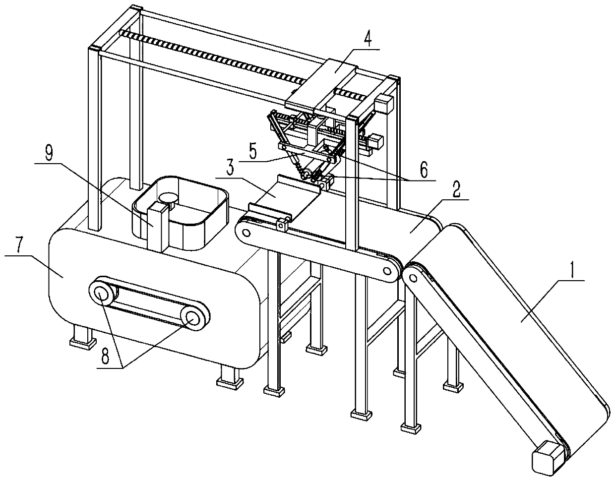
[0029] Such as Figure 1-8 As shown, a mixing device for civil engineering construction includes a housing 7, a shaft IV 8, a stirring blade 801, a motor IV 802, a mounting seat 9, an electric push rod II 901, a motor V 902 and a cutting blade 903. The upper end of the housing 7 is provided with There is a material inlet, and the casing 7 is rotated to connect two shafts Ⅳ8, and the two shafts Ⅳ8 are synchronously connected. The motor Ⅴ902 is fixed on the outer end of the casing 7, and the output shaft of the motor Ⅴ902 is fixedly connected to one of the shafts Ⅳ8. The mounting base 9 Fixed on the shell 7, the electric push rod II901 is fixed on the mounting base 9, the motor V902 is fixed on the movable end of the electric push rod II901, the output shaft of the motor V902 is fixed on the cutting piece 903, and the cutting piece 903 is located on the directly above the inlet. The stirring blade 801 is used to stir the materials in the shell 7, for example, mixing the raw mat...

specific Embodiment approach 2

[0031] Such as Figure 1-8 As shown, the mixing device for civil engineering construction also includes a belt conveyor I1 and a belt conveyor II2, and the belt conveyor I1 is used to transport the bagged material to the height of the inlet and transport it to the On the conveyor II2, the belt conveyor II2 is used to transport the bagged material to the side of the inlet. refer to figure 1 Place the wide side of the bagged raw material from front to back and the long side from left to right on the belt conveyor Ⅰ1, start the belt conveyor Ⅰ1 to drive the bagged raw material to move to the upper left until it moves to the belt conveyor Ⅱ2 , start the belt conveyor II 2 to drive the bagged raw materials to move to the left close to the material inlet, so as to realize the automatic transportation of the bagged raw materials according to the expected placement form.

specific Embodiment approach 3

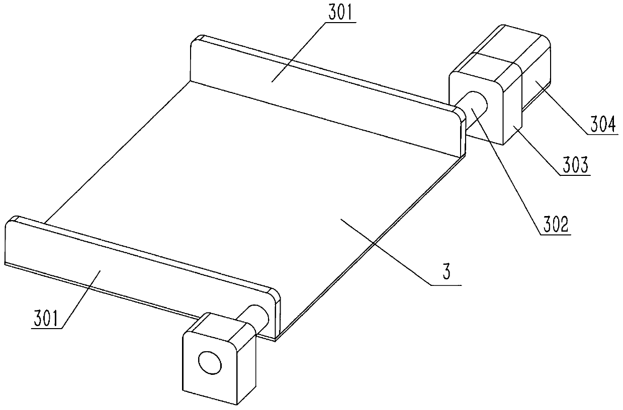
[0033] Such as Figure 1-8As shown, the mixing device for civil engineering construction also includes a half board 3, a rotating part 301, a shaft I302, a shaft seat I303 and a motor I304, and the front and rear ends of the half board 3 are respectively fixed with a rotating part 301 and two The outer ends of the rotating part 301 are fixedly connected with a shaft I302, and the two shafts I302 are located at the right end of the half plate 3. The two shafts I302 are respectively connected to the two shaft seats I303 in rotation, and the motor I304 is fixedly connected to one of the shaft seats I303. , the output shaft of the motor I304 is fixedly connected to one of the shafts I302; the half plate 3 is arranged on the upper end of the belt conveyor II2 and is arranged close to the inlet, and the distance between the half plate 3 and the belt conveyor II2 is 1 to 5mm. Start the motor I304, the output shaft of the motor I304 drives the shaft I302 to rotate, and the shaft I302 ...


PUM


Abstract

The invention relates to the field of material mixing, in particular to a material mixing device for civil construction. The device comprises a shell, shafts IV, stirring blades, a motor IV, a mounting base, an electric push rod II, a motor V and a cutting blade. Two rubber rollers can automatically take away a bagged material after clamping a sealing opening through linear contact, the action issmooth, pause shaking is reduced, and the bagged material is prevented from falling off due to shaking after other mechanisms for taking away the bagged material are started or stopped. A manipulatorcan continuously drive the bag to be separated from the feeding opening and then release the bag, and the bag is convenient to recycle. After the lower end of the bagged material is cut by the vertical cutting blade, the bag is easy to reuse, and the material in the bag can be completely released without residues. The rotating directions of the two spiral blades are opposite, and the mixed material can be stirred and pushed in two directions during synchronous rotation, so that the mixed material stirring effect is better.

Description

technical field [0001] The invention relates to the field of mixing materials, in particular to a mixing device for civil construction. Background technique [0002] For example, the publication number is CN107803137A, which is a kind of mixing device for building construction, including a base, the bottom of the base is fixedly equipped with a support block, the bottom of the support block is fixedly connected with universal wheels, and the top of the base is fixedly connected with A discharge box, the inside of the discharge box is fixedly connected with a first baffle, the bottom of the discharge box is fixedly connected with a discharge port, and the outer surface of the discharge box is fixedly connected with a first motor. The first motor is connected with the first driving gear through the first transmission shaft provided at one end. In this invention, by setting four material inlets, the classification of mixing materials is very clear. Different materials are put ...

Claims


Application Information

Patent Timeline
Patent Type & Authority Applications(China)
IPC IPC(8): B01F15/02
CPCB01F35/7131B01F35/71775
Inventor 程小春
Owner ZHEJIANG GUANGSHA COLLEGE OF APPLIED CONSTRTECH
Why Eureka
Try Eureka