
Buffer device for lift car of elevator shaft

A buffer device and elevator shaft technology, applied in the elevator field, can solve the problems of elevator speed reduction, passenger injury, endangering life and safety, etc., and achieve the effect of reducing speed and improving buffering effect.

Pending Publication Date: 2020-05-29
河南省龙基建设工程有限公司
View PDF4 Cites 10 Cited by
  • Summary
  • Abstract
  • Description
  • Claims
  • Application Information

AI Technical Summary

Problems solved by technology

[0002] With the advancement of urbanization, more and more people are migrating to the city. The limited land in the city has to build higher and higher buildings in order to accommodate the huge number of people. Elevators, as a means of vertical transportation in high-rise buildings, have experienced hundreds of years. With the development of the development, its safety protection has been perfected day by day. However, due to various reasons, accidents of elevators falling and squatting at the bottom still occur from time to time. The buffering device can only work when the freight elevator falls to the bottom of the well, and cannot reduce the speed of the elevator during the falling process, and if the elevator falls too fast, even if there is a buffering device at the bottom of the well, it may be difficult to avoid trapped people Injury, at present, the bases for installing buffers on the market are basically rigid structures, which are only used to install and fix buffers. In the event of a squatting accident, the elevator car can only be buffered by the buffer installed above it, reducing the For the injury of passengers, although this structure can reduce the degree of construction injury, the degree of reduction of accident injury is limited. The existing buffer device is not conducive to reducing the hazard of elevator falling, and cannot meet the needs of elevator operation safety

Method used


Image

  • Buffer device for lift car of elevator shaft
  • Buffer device for lift car of elevator shaft
  • Buffer device for lift car of elevator shaft

Examples


Embodiment 1

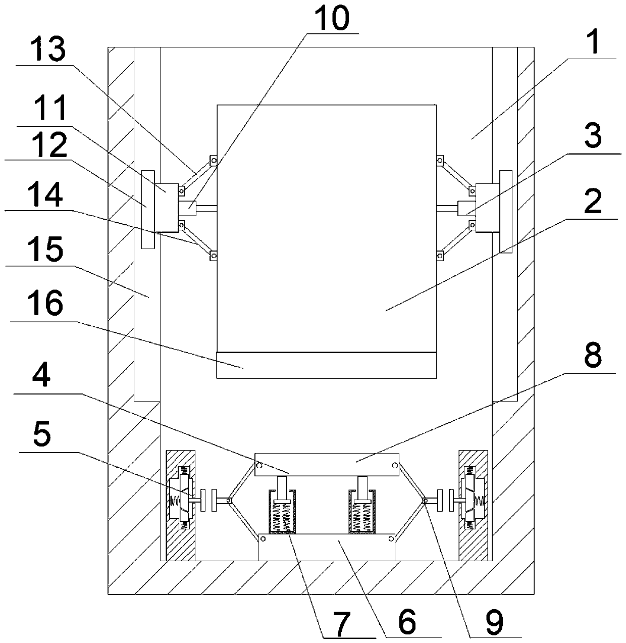
[0025] like figure 1 , Figure 4 As shown, an elevator shaft car buffer device includes a deceleration mechanism 3 that is movably connected to the side wall of the elevator shaft 1 and the side wall of the car 2, is located directly below the car 2 and is fixedly connected to the bottom of the elevator shaft 1 The first buffer mechanism 4 of the first buffer mechanism 4, the second buffer mechanism 5 corresponding to the left and right sides of the first buffer mechanism 4 and the first buffer mechanism 4, the setting of the deceleration mechanism 3, when the car 2 fell, the deceleration mechanism 3 increased The friction force with the side wall of the elevator shaft 1 is large, the falling speed of the car 2 is reduced, and the falling of the car is buffered. The first buffer mechanism 4 and the second buffer mechanism 5 are both energy storage type buffer devices. The first buffer mechanism can fan most of the impact force, and the second buffer mechanism 5 can disperse m...

Embodiment 2

[0030] like Figure 5 and Figure 4 As shown, an elevator shaft car buffer device includes a deceleration mechanism 3 that is movably connected to the side wall of the elevator shaft 1 and the side wall of the car 2, is located directly below the car 2 and is fixedly connected to the bottom of the elevator shaft 1 The first buffer mechanism 4 of the first buffer mechanism 4, the second buffer mechanism 5 corresponding to the left and right sides of the first buffer mechanism 4 and the first buffer mechanism 4, the setting of the deceleration mechanism 3, when the car 2 fell, the deceleration mechanism 3 increased The friction force with the side wall of the elevator shaft 1 is large, the falling speed of the car 2 is reduced, and the falling of the car is buffered. The first buffer mechanism 4 and the second buffer mechanism 5 are both energy storage type buffer devices. The first buffer mechanism can fan most of the impact force, and the second buffer mechanism 5 can dispers...


PUM


Abstract

The invention discloses a buffer device for a lift car of an elevator shaft. The buffer device comprises speed reducing mechanisms movably connected with the side wall of the elevator shaft and the side wall of the lift car, a first buffer mechanism positioned under the lift car and fixedly connected with the bottom of the elevator shaft, and second buffer mechanisms positioned on the left side and the right side of the first buffer mechanism and corresponding to the first buffer mechanism, wherein the number of the speed reducing mechanisms and the second buffer mechanism are each two. The two speed reducing mechanisms are positioned on the left side surface and the right side surface of the lift car, and the two second buffer mechanisms are symmetrically arranged on the left side and theright side of the first buffer mechanism respectively. Through the arrangement of the speed reducing mechanism, the elevator falling speed is reduced, and therefore a better buffering effect is achieved on elevator falling; and through the arrangement of the first buffer mechanism and the second buffer mechanisms, impact damage to passengers caused by large resilience force generated by the buffer device under impact force is prevented.

Description

technical field [0001] The invention relates to the technical field of elevators, in particular to an elevator shaft car buffer device. Background technique [0002] With the advancement of urbanization, more and more people are migrating to the city. The limited land in the city has to build higher and higher buildings in order to accommodate the huge number of people. Elevators, as a means of vertical transportation in high-rise buildings, have experienced hundreds of years. With the development of the development, its safety protection has been perfected day by day. However, due to various reasons, accidents of elevators falling and squatting at the bottom still occur from time to time. The buffering device can only work when the freight elevator falls to the bottom of the well, and cannot reduce the speed of the elevator during the falling process, and if the elevator falls too fast, even if there is a buffering device at the bottom of the well, it may be difficult to av...

Claims


Application Information

Patent Timeline
Patent Type & Authority Applications(China)
IPC IPC(8): B66B5/18B66B5/28
CPCB66B5/282B66B5/18
Inventor 李杨贾海艳郑波黄芳
Owner 河南省龙基建设工程有限公司
Features
  • Generate Ideas
  • Intellectual Property
  • Life Sciences
  • Materials
  • Tech Scout
  • Unparalleled Data Quality
  • Higher Quality Content
  • 60% Fewer Hallucinations
Learn More