Electric power fence

A fence and electricity technology, applied in the field of fence, can solve the problems of easy injury, inconvenient disassembly, simple structure, etc., and achieve the effect of easy disassembly and assembly

Inactive Publication Date: 2020-05-29
赤壁市亿德汽车配件有限公司
View PDF0 Cites 0 Cited by
  • Summary
  • Abstract
  • Description
  • Claims
  • Application Information

AI Technical Summary

Problems solved by technology

The existing electric fences have a simple structure, most of them can only move laterally, and their protection ability is weak; some electric fences can be twisted horizontally at the same time, but they are easy to cause injuries during the protection process and are not easy to disassemble
In addition, when the power operation needs to surround a large area, the connection between the fences is not convenient.
[0003] For the problems in related technologies, no effective solutions have been proposed yet

Method used


Image

  • Electric power fence

Examples


Embodiment Construction

[0017] The following will clearly and completely describe the technical solutions in the embodiments of the present invention with reference to the accompanying drawings in the embodiments of the present invention. Obviously, the described embodiments are only some, not all, embodiments of the present invention. All other embodiments obtained by persons of ordinary skill in the art based on the embodiments of the present invention belong to the protection scope of the present invention.

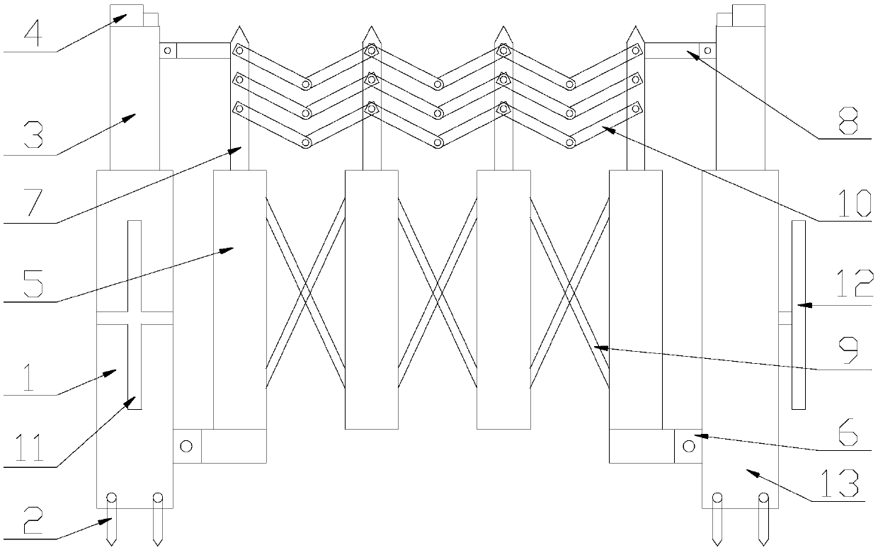
[0018] Such as figure 1 As shown, an electric fence according to an embodiment of the present invention includes a first support column 1, a second support column 13, a first vertical rail 5 and a diagonal stay rod 9, and the first support column 1, the second support column The bottom ends of the columns 13 are all hinged with positioning pins 2, the insides of the first support column 1 and the second support column 13 are equipped with actuators, and the top ends of the first support colum...


PUM

PropertyMeasurementUnit
Heightaaaaaaaaaa

Abstract

The invention discloses an electric power fence. The electric power fence comprises a first supporting column, a second supporting column, first vertical bars and diagonal draw bars. Locating pins arehinged with the bottom ends of the first supporting column and the second supporting column, executive devices are installed inside the first supporting column and the second supporting column, telescopic columns are installed at the top ends of the first supporting column and the second supporting column, and the bottom ends of the telescopic columns are connected with the executive devices. Laser sensors are arranged at the top ends of the telescopic columns and connected with the executive devices through wires. First transverse rods are connected with the two corresponding ends of the first vertical bars and connected with the bottoms of the first supporting column and the second supporting column, and the first vertical bars are connected in sequence through the diagonal draw bars. Second vertical bars are arranged on the first vertical bars, and second transverse rods are connected with the two corresponding ends of the second vertical bars and connected with the tops of the telescopic columns. Multiple rotating pairs are arranged on the second vertical bars and connected with two-connecting-rod assemblies, and the second vertical bars are connected through the two-connecting-rod assemblies.

Description

technical field [0001] The invention relates to the technical field of fences, in particular to an electric fence. Background technique [0002] Electric fences are widely used in electric power operations and are essential safety protection tools. Electric fences are mainly used in power plants, substation electrical equipment maintenance, electrical experiments, power distribution maintenance, etc. Commonly used are stainless steel belt type, fiberglass sheet type, tubular type and nylon fence. In some high-risk operations, electric fences are even more important, and their functional requirements are particularly high. The existing electric fences have a simple structure, most of them can only move laterally, and their protection ability is weak; some electric fences can be twisted horizontally at the same time, but they are easy to cause injuries during the protection process and are not easy to disassemble. In addition, when the electrical work needs to surround a la...

Claims


Application Information

Patent Timeline
IPC IPC(8): E04H17/14E04H17/20
CPCE04H17/14E04H17/20
Inventor 钱金河
Owner 赤壁市亿德汽车配件有限公司
Why Eureka
Try Eureka