Optical element adjusting frame

A technology of optical components and adjustment mounts, applied in the field of optics, can solve problems such as difficulties, Z-axis translation cannot be adjusted independently, optical path crosstalk, etc., and achieve the effect of compact and practical structure, improved convenience and stability, and avoiding optical crosstalk

Pending Publication Date: 2020-05-29
长沙麓邦光电科技有限公司
View PDF5 Cites 3 Cited by
  • Summary
  • Abstract
  • Description
  • Claims
  • Application Information

AI Technical Summary

Problems solved by technology

The common multi-dimensional adjustment mounts on the market can realize five-degree-of-freedom adjustment without optical crosstalk, but lack the freedom adjustment around the Z-axis, and cannot be compatible with the use of polarizers and wave plates
Part of the six-axis optical adjustment mount can realize six-degree-of-freedom adjustment, but its Z-axis translation cannot be adjusted independently. It needs to be adjusted at the same time by adjusting the three adjusters at the rear end to move the same distance, and it is necessary to ensure that the three adjusters move the same distance along the Z-axis. Difficult; at the same time, adjusting the rotation of the XY axis also needs to adjust the two adjusters at the rear end, which will inevitably affect the translation of the Z axis, causing crosstalk in the optical path, and thus requires multiple adjustments to meet the system requirements

Method used


Image

  • Optical element adjusting frame
  • Optical element adjusting frame
  • Optical element adjusting frame

Examples


Embodiment 1

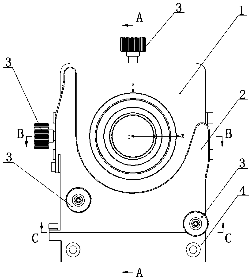
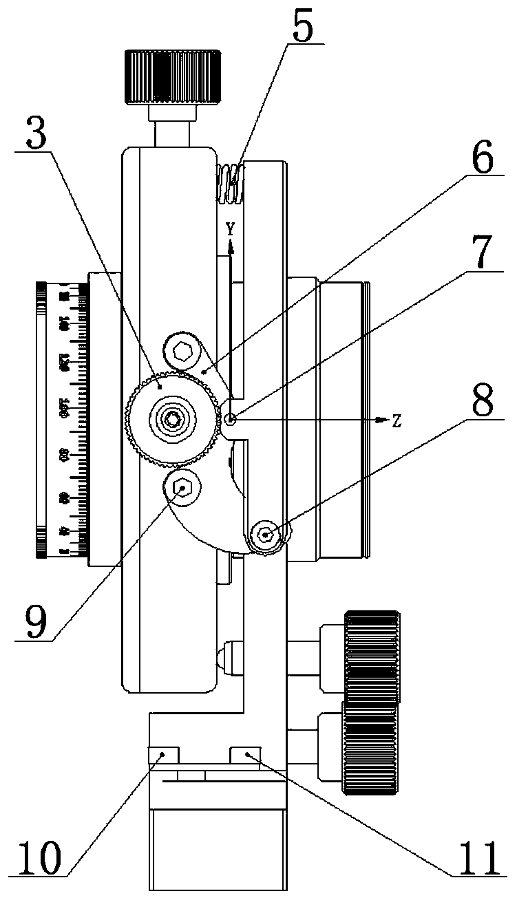
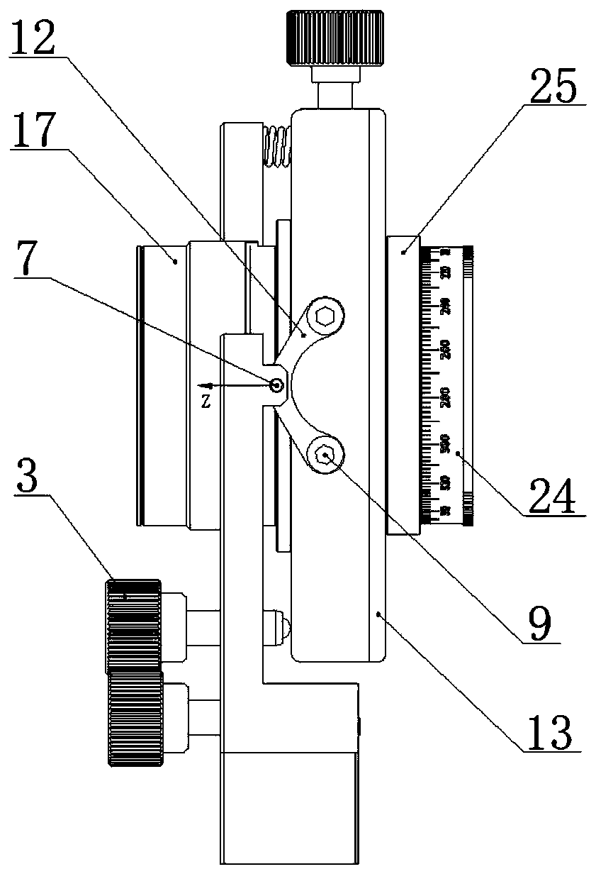
[0032] This embodiment discloses an optical element adjustment frame.

[0033] Such as Figure 1 to Figure 7 As shown, the adjustment frame of this embodiment includes: a support frame 1, a rotating frame 2, a hand screw 3, a base 4, a compression spring 5, a right pitch bracket 6, a cylindrical pin 7, a locking screw 8, a fixing screw 9, a locking screw Block 10, locking screw 11, left pitch bracket 12, rear cover 13, optical element mounting ring 14, snap ring 15, cover 16, front knob 17, limit ring 18, first jacking screw 19, connecting ring 20 , limit block 21, translation ring 22, second top wire 23, rear knob 24, locking ring 25, pagoda spring 26, rotating pin 27, compression spring 28, limit screw 29, limit pin 30.

[0034] In this embodiment, the optical element is installed in the optical element mounting ring 14, and is fixed by pressing the snap ring 15. The mounting ring has a positioning step. When the mounting ring is translated to the final position, the positi...


PUM


Abstract

The invention relates to the technical field of optics, and discloses an optical element adjusting frame which is used for independently adjusting and locking all dimensions and improving the convenience and stability of operation while avoiding optical crosstalk. The adjusting frame comprises a supporting frame, a first driving mechanism and a second driving mechanism, wherein the supporting frame is provided with a translation ring, the first driving mechanism drives the translation ring to translate towards the X axis, and the second driving mechanism drives the translation ring to translate towards the Y axis. A translation ring is connected with the connecting ring through internal threads. A connecting ring is coupled with the optical element mounting ring, the front knob, the limiting ring, the locking ring, the translation ring and the rear knob. A first jackscrew is arranged between the limiting ring and the front knob, and a second jackscrew is arranged between the locking ring and the rear knob. When the second jackscrew is locked and the first jackscrew is loosened, the optical element mounting ring is driven to translate in the Z-axis direction by rotating the front knob. When the first jackscrew is locked and the second jackscrew is loosened, the rear knob is rotated to drive the optical element mounting ring to rotate around the Z axis.

Description

technical field [0001] The invention relates to the field of optical technology, in particular to an optical element adjustment frame. Background technique [0002] Optical adjustment mounts are widely used in the field of optical precision machinery, and related technologies include but are not limited to existing technologies disclosed in patents such as 201710000695.7, 201610333357.0, 201821640358.0, 201210300153.9, and 200820206058.1. The optical components are installed in the adjustment frame to fine-tune the azimuth of the optical axis, the focus of the spot, etc., so as to realize the function of the optical system. [0003] The more adjustable degrees of freedom the adjustment frame has, the more simplified the volume of the optical system and the more convenient the adjustment. The multi-dimensional adjustment mounts that are common on the market can realize five-degree-of-freedom adjustment without optical crosstalk, but lack the degree-of-freedom adjustment arou...

Claims


Application Information

Patent Timeline
Patent Type & Authority Applications(China)
IPC IPC(8): G02B7/00
CPCG02B7/00
Inventor 杨志维李晓春池奕宾何志纲代林茂
Owner 长沙麓邦光电科技有限公司
Why Eureka
Try Eureka