
Charging equipment allocation method and terminal equipment

A technology of charging equipment and distribution method, applied in the field of computers, can solve problems such as robot damage, and achieve the effects of avoiding scratches and collisions, improving charging efficiency, and avoiding damage

Active Publication Date: 2022-04-15
UBTECH ROBOTICS CORP LTD
View PDF10 Cites 0 Cited by
  • Summary
  • Abstract
  • Description
  • Claims
  • Application Information

AI Technical Summary

Problems solved by technology

[0003] In view of this, the embodiment of the present invention provides a charging equipment distribution method and terminal equipment to solve the current problem that multiple robots move to the same charging equipment to charge and cause damage to the robot

Method used


Image

  • Charging equipment allocation method and terminal equipment
  • Charging equipment allocation method and terminal equipment
  • Charging equipment allocation method and terminal equipment

Examples


Embodiment Construction

[0023] In the following description, specific details such as specific system structures and technologies are presented for the purpose of illustration rather than limitation, so as to thoroughly understand the embodiments of the present invention. It will be apparent, however, to one skilled in the art that the invention may be practiced in other embodiments without these specific details. In other instances, detailed descriptions of well-known systems, devices, circuits, and methods are omitted so as not to obscure the description of the present invention with unnecessary detail.

[0024] In order to illustrate the technical solutions of the present invention, specific examples are used below to illustrate.

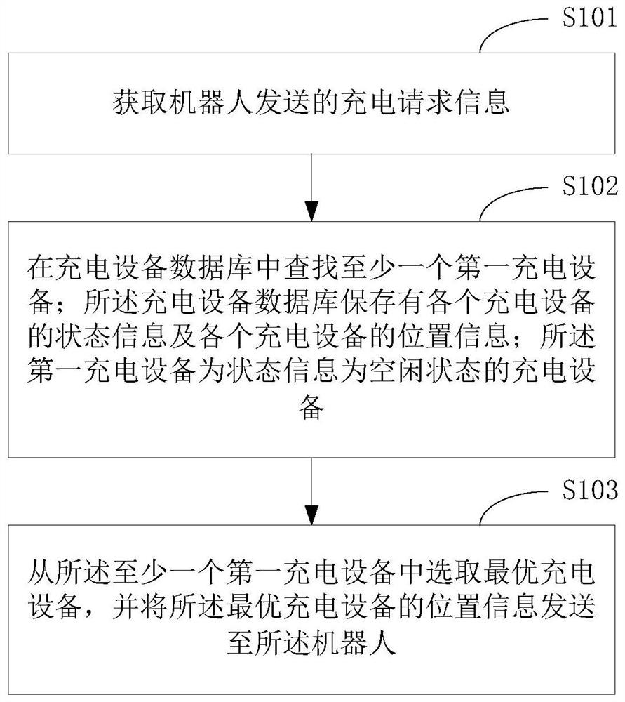
[0025] figure 1 The implementation flowchart of the method for allocating charging equipment provided by the embodiment of the present invention is described in detail as follows:

[0026] In S101, the charging request information sent by the robot is acquired.

[00...


PUM


Abstract

The invention relates to the technical field of computers, and provides a method for distributing charging equipment and terminal equipment. The method includes: obtaining the charging request information sent by the robot; searching for at least one first charging device in the charging device database; the charging device database stores the status information of each charging device and the location information of each charging device; the first The charging device is a charging device whose status information is in an idle state; an optimal charging device is selected from the at least one first charging device, and the position information of the optimal charging device is sent to the robot. The invention can rationally allocate the use rights of the charging equipment, avoid the phenomenon that multiple robots move to the same charging equipment to charge and compete for the same charging position, avoid the phenomenon of robot scratching and collision, and avoid damage to the robots.

Description

technical field [0001] The invention relates to the field of computer technology, in particular to a method for distributing charging equipment and a terminal equipment. Background technique [0002] At present, the robot can move to the charging position when it needs to be charged, and charge through charging equipment (such as charging piles, etc.). However, in some scenarios where there are multiple robots, if multiple robots need to be charged at the same time, it may cause multiple robots to move to the same charging device for charging, and scratches and collisions of the robots may occur, causing damage to the robots. Contents of the invention [0003] In view of this, the embodiment of the present invention provides a charging equipment allocation method and a terminal device to solve the current problem that multiple robots move to the same charging equipment to charge and cause damage to the robots. [0004] The first aspect of the embodiments of the present in...

Claims


Application Information

Patent Timeline
Patent Type & Authority Patents(China)
IPC IPC(8): H02J7/00
CPCY02E60/10
Inventor 熊友军张吉猛
Owner UBTECH ROBOTICS CORP LTD
Learn More