Laser heating tin wire feeding drag welding process

A technology of laser heating and tin wire feeding, which is applied in tin feeding devices, metal processing equipment, electric heating devices, etc., can solve the problems of soldering iron tip wear, increased difficulty of automatic welding, and poor welding, so as to improve production efficiency and facilitate automation The effect of mass production

Inactive Publication Date: 2020-06-02
深圳市华瀚激光科技有限公司
View PDF7 Cites 2 Cited by
  • Summary
  • Abstract
  • Description
  • Claims
  • Application Information

AI Technical Summary

Problems solved by technology

During the soldering process of the electric soldering iron, the tip of the soldering iron must always be in contact with the component pins. Due to friction and corrosion of the flux, the tip of the soldering iron will wear out quickly, resulting in poor soldering. The tip of the soldering iron must be replaced almost every day. , which greatly increases the difficulty of automated welding

Method used


Image

  • Laser heating tin wire feeding drag welding process
  • Laser heating tin wire feeding drag welding process
  • Laser heating tin wire feeding drag welding process

Examples


Embodiment Construction

[0028] The technical solutions in the embodiments of the present invention will be further described below in conjunction with the embodiments of the present invention and the accompanying drawings.

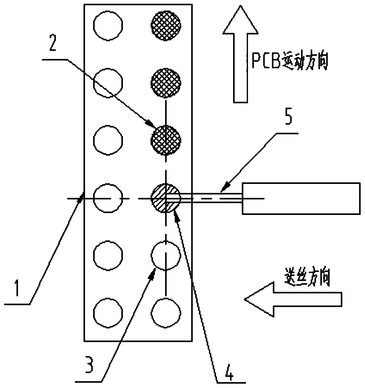
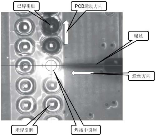
[0029] The laser heating tin wire drag welding process of the present invention adopts the laser tin wire welding equipment in the prior art. This equipment is usually used as single-point welding. After a large number of experiments and skills have been mastered, it can be used to realize the laser drag welding process of the present invention. The specific operation steps are as follows:

[0030] The first step is to adjust the size of the laser focus on the device to match the size of the solder joints that need to be welded. During implementation, the diameter of the laser focus ranges from 0.3 mm to 2.0 mm. Within this range, the laser energy can well correspond to tin wires 5 of different diameters. If the spot is too small, it is easy to burn the pad 1. If the spot is too ...


PUM

PropertyMeasurementUnit
diameteraaaaaaaaaa
diameteraaaaaaaaaa

Abstract

The invention discloses a laser heating tin wire feeding drag welding process. Laser tin wire welding equipment is adopted. The laser heating tin wire feeding drag welding process comprises the following specific steps of 1, adjusting the size of a laser focus on the equipment to be matched with the size of a welding spot of a pin of a product; 2, selecting the diameter of a tin wire to match thesize of the welding spot of the pin of the product; 3, adjusting the included angle between the arrangement directions of the tin wire and the welding spot of the pin of the product; 4, setting laserpower curve parameters on the equipment; 5, setting the wire feeding speed of the equipment for feeding the tin wire to the laser focus; 6, setting the moving speed of the product or the laser focus on the equipment; 7, setting a movement route of the product, and enabling a welding spot of an unwelded pin to be sequentially overlapped with the laser focus; and 8, when welding is started, sequentially conveying the welding spot of the unwelded pin to the position below the laser focus, and meanwhile conveying the tin wire to the position below the laser focus till all the welding spots of thepins are welded. Abrasion of a soldering bit is avoided, automatic welding is achieved, and the quality stability is improved.

Description

technical field [0001] The invention relates to a laser-heated tin-feeding wire drag welding process, which belongs to the technical field of tin drag welding. Background technique [0002] At present, there are often some electronic components and IC chips on the circuit board, and their pins are the same size as the pads on the bottom board. When soldering, we use a soldering iron as a heat source and apply flux to the pins to be soldered in advance. (if necessary), and then add tin wire while dragging for soldering, usually moving in the same direction, this method is usually called electric soldering iron drag welding. During the soldering process of the electric soldering iron, the tip of the soldering iron must always be in contact with the component pins. Due to friction and corrosion of the flux, the tip of the soldering iron will wear out quickly, resulting in poor soldering. The tip of the soldering iron must be replaced almost every day. , resulting in greatly in...

Claims


Application Information

Patent Timeline
Patent Type & Authority Applications(China)
IPC IPC(8): B23K1/00B23K1/005B23K3/04B23K3/06
CPCB23K1/0016B23K1/0056B23K3/04B23K3/063
Inventor 王兰锋
Owner 深圳市华瀚激光科技有限公司
Why Eureka
Try Eureka