Vertical driller chipping collection tool

A vertical drilling machine and debris technology, applied in the direction of manufacturing tools, metal processing equipment, metal processing machinery parts, etc., can solve the problem that debris is not easy to clean and collect

Inactive Publication Date: 2020-06-02
老河口市生龙机械有限公司
View PDF9 Cites 0 Cited by
  • Summary
  • Abstract
  • Description
  • Claims
  • Application Information

AI Technical Summary

Problems solved by technology

[0003] The purpose of the present invention is to solve the shortcoming that debris is not easy to clean and collect in the prior art, and the proposed vertical drilling machine debris collection tool

Method used


Image

  • Vertical driller chipping collection tool
  • Vertical driller chipping collection tool
  • Vertical driller chipping collection tool

Examples


Embodiment 1

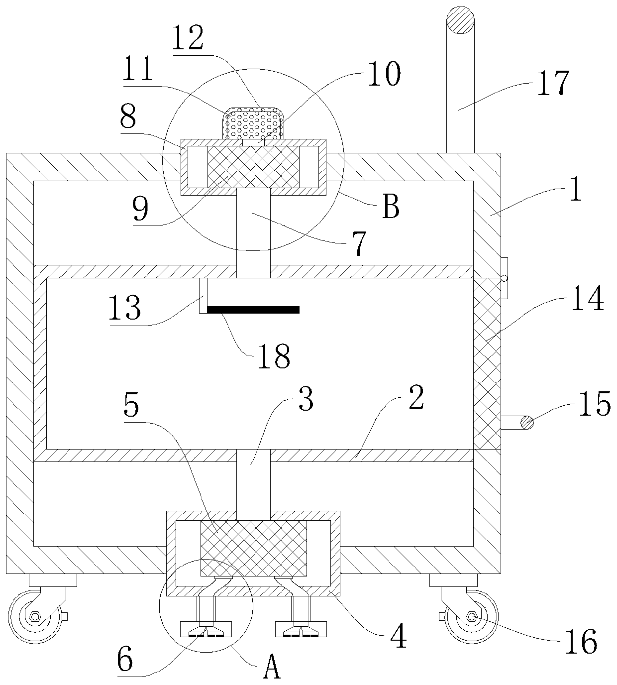
[0018] refer to Figure 1-3 , a vertical drilling machine debris collection tool, including an outer box 1, an armrest 17 is fixedly installed on one side of the upper surface of the outer box 1, and the device can be moved through the handrail 17, and a collection box 2 is fixedly installed inside the outer box 1 to collect The box 2 is used to collect debris and dust. One side of the collection box 2 is installed with a door 14 through hinge rotation, and a handle 15 is fixedly installed on the outside of the door 14. The door 14 can be opened through the handle 15. The upper end of the collection box 2 is fixed and connected. A second inlet pipe 7 is provided, and a second suction fan 9 is fixedly installed on the upper end of the second inlet pipe 7 .

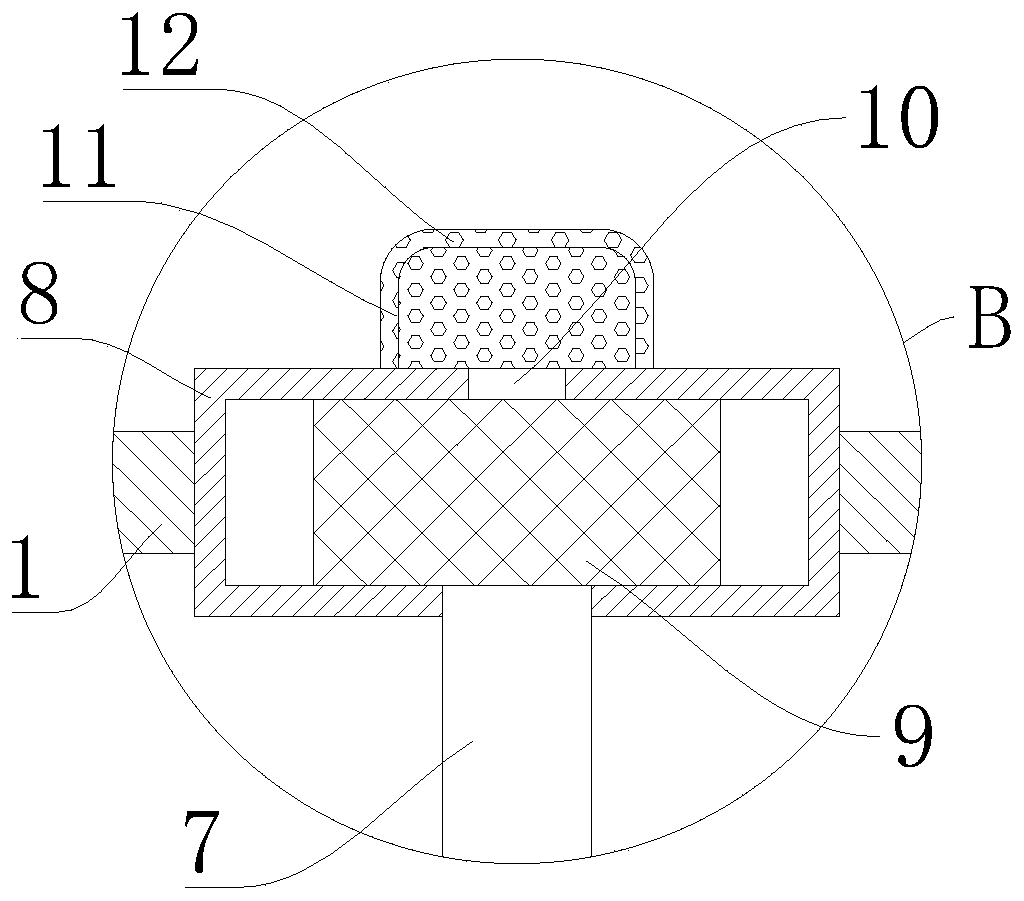
[0019] The second suction fan 9 is fixedly installed in the second fixed frame 8, and the second fixed frame 8 is fixedly installed inside the upper surface of the outer box body 1. The upper end of the second suction fan 9...

Embodiment 2

[0024] refer to figure 1 As another preferred embodiment of the present invention, the difference from Embodiment 1 is that a fixed frame 13 is fixedly installed on the inner wall surface above the collection box 2, and a wet sponge cover 18 is set on the outside of the fixed frame 13, and the wet sponge cover 18 is located at the second Below the secondary pipe 7, the wet sponge cover 18 can purify the wind with dust blown in from the second suction fan 9, so that the dust is stained on the wet sponge, preventing the dust from scattering and affecting the collection effect.


PUM


Abstract

The invention relates to the technical field of drillers, in particular to a vertical driller chipping collection tool. The vertical driller chipping collection tool comprises an outer box body, and acollection box is fixedly installed in the outer box body; one side of the collection box is rotationally provided with a sealing door through a hinge, and the outer side of the sealing door is fixedly provided with a handle; the upper end of the collection box is fixedly provided with a second inlet pipe in a communicating mode, and the upper end of the second inlet pipe is fixedly provided witha second suction fan; the second suction fan is fixedly installed in a second fixing frame, and the second fixing frame is fixedly installed in the upper surface of the outer box body; the upper endof the second suction fan is fixedly provided with a connection pipe, and the upper end of the connection pipe penetrates and extends to the upper side of the outer box body; a pierced cover is fixedly installed on the upper surface of the outer box body and located on the outer side of the connection pipe; and the lower end of the collection box is fixedly provided with a first inlet pipe in a communicating mode. The collection tool is good in collection effect and worthy of popularization.

Description

technical field [0001] The invention relates to the technical field of drilling machine work, in particular to a debris collection tool for a vertical drilling machine. Background technique [0002] During the working process of the vertical drilling machine, there will be a lot of debris. The accumulation of these debris will affect the normal work. These debris are not easy to clean, and the staff need to spend more time on cleaning, which is time-consuming and laborious. Therefore, it is necessary to Collect this debris to keep your work environment tidy. Contents of the invention [0003] The object of the present invention is to solve the shortcoming that debris is not easy to clean and collect in the prior art, and proposes a debris collection tool for a vertical drilling machine. [0004] In order to achieve the above object, the present invention adopts the following technical solutions: [0005] A vertical drilling machine debris collection tool is designed, inc...

Claims


Application Information

Patent Timeline
Patent Type & Authority Applications(China)
IPC IPC(8): B23Q11/00
CPCB23Q11/0046
Inventor 杨冰蔡国旺
Owner 老河口市生龙机械有限公司
Why Eureka
Try Eureka