
Pedestrian protection structure for automobile and automobile

A technology for pedestrian protection and automobiles, which is applied in the directions of pedestrian/occupant safety arrangement, vehicle components, vehicle safety arrangement, etc. It can solve the problems of increasing the weight of the front end of the vehicle, the level of light weight is not high, and the shape restriction is more, and achieves the realization of light weight. , Improve pedestrian protection performance, optimize the effect of the structure

Active Publication Date: 2021-08-31
DONGFENG MOTOR CORP HUBEI
View PDF9 Cites 0 Cited by
  • Summary
  • Abstract
  • Description
  • Claims
  • Application Information

AI Technical Summary

Problems solved by technology

[0003] Chinese patent application CN203186285U discloses a car pedestrian calf protection structure. In this patent, the lower support structure of the calf is transferred to the car body through the metal water tank lower beam. Since the water tank frame is designed as a sheet metal part, the overall weight is relatively heavy, increasing The weight of the front end of the vehicle is reduced; and, in order to effectively support the lower leg support frame, the structure at the lower beam of the water tank also needs to be designed to be stronger or to be supported by a separate design bracket, which increases the number of parts
[0004] In addition, in some other schemes, the calf protection bracket is welded to the front anti-collision beam. Since the calf protection bracket is designed as a sheet metal part, the lightweight level is not high, and the structural design and layout also have more restrictions on the shape

Method used


Image

  • Pedestrian protection structure for automobile and automobile
  • Pedestrian protection structure for automobile and automobile
  • Pedestrian protection structure for automobile and automobile

Examples


Embodiment Construction

[0035] The present invention will be described in further detail below in conjunction with the accompanying drawings and embodiments.

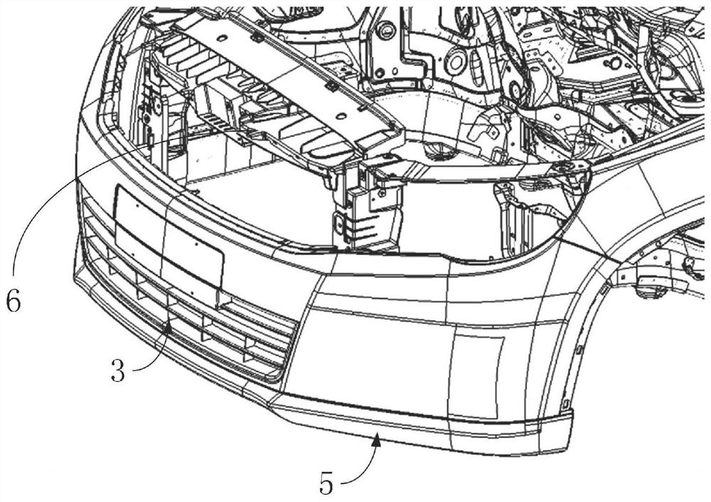
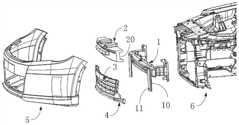
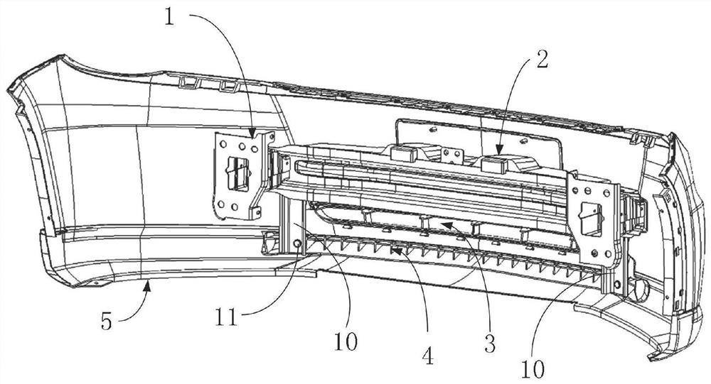
[0036] see figure 1 and figure 2 As shown, in some preferred embodiments, a pedestrian protection structure for automobiles is provided. When in use, the pedestrian protection structure for automobiles is arranged between the bumper skin 5 and the longitudinal beam 6, specifically, the pedestrian protection structure for automobiles The protective structure includes a front anti-collision beam 1, an energy-absorbing member 2, a lower grille 3 and a calf support crossbeam 4, wherein the two ends of the front anti-collision beam 1 are respectively provided with a side support bracket 10; On the impact beam 1, and located on the side of the front anti-collision beam 1 facing the bumper skin 5; the lower grille 3 is located on the side of the front anti-collision beam 1 facing the bumper skin 5; the calf support beam 4 and the lower grille 3 is...


PUM


Abstract

The invention discloses a pedestrian protection structure for an automobile and an automobile. The pedestrian protection structure for the automobile is used to be arranged between the bumper skin and the longitudinal beam. The pedestrian protection structure for the automobile includes a front anti-collision beam, an energy absorbing part, The lower grille and the lower leg support crossbeam, and the two ends of the front anti-collision beam are respectively equipped with one side support bracket; the energy absorbing parts are arranged on the front anti-collision beam, and are located side; the lower grille is located on the side of the front anti-collision beam facing the bumper skin; the lower leg support beam is integrally formed with the lower grille and is located at the lower part of the lower grille, and the two ends of the lower leg support beam are respectively Connect with the support brackets on both sides. In the present invention, the lower leg support beam is directly integrated with the lower grille, avoiding the separate design of the lower leg support beam, and reducing the number of parts. At the same time, in the manufacturing process, the manufacturing process is relatively simple due to the integral molding.

Description

technical field [0001] The invention relates to the technical field of automobile manufacturing, in particular to an automobile pedestrian protection structure and an automobile. Background technique [0002] With the continuous development of the automobile industry, automobiles have become an indispensable part of the life of the public. However, with the increase of automobiles, traffic accidents are also increasing, and the automobile industry has higher and higher requirements for the safety performance of automobiles. During a collision between a person and a vehicle, the front bumper of a car is the main structure that causes injury to the lower limbs of a pedestrian. When an accident occurs, the lower leg of the pedestrian first directly collides with the front bumper, and the tibia bears the direct collision force. Due to the delay of the tibia, This in turn results in a shear load in addition to the bending load in the knee joint area. In response to the above pro...

Claims


Application Information

Patent Timeline
Patent Type & Authority Patents(China)
IPC IPC(8): B60R21/34
CPCB60R21/34
Inventor 刘小杰丁瑞阳叶勤申中一袁慧森
Owner DONGFENG MOTOR CORP HUBEI
Learn More