A tie rod seat, car body and rail vehicle
A technology of tie rod seat and car body, which is applied in the field of rail vehicles, and can solve problems such as difficult maintenance, deformation of tie rod seat, twisting and deformation of car body side beams, etc.
- Summary
- Abstract
- Description
- Claims
- Application Information
AI Technical Summary
Problems solved by technology
Method used
Image

Examples
Embodiment 1
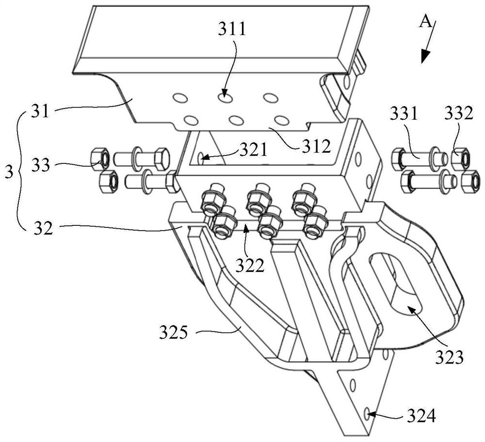
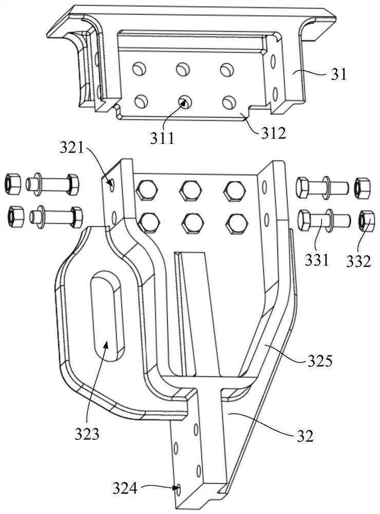
[0035] The embodiment of this application provides a tie rod seat 3, please refer to figure 1 and figure 2 , the rod seat 3 is a split structure, and includes a base 31 and a connecting seat 32; the base 31 is used for fixed connection with the vehicle body 1; the top of the connecting seat 32 is detachably connected to the bottom of the base 31, and the connecting seat 32 is provided with a connecting structure for installing the bogie 2 . Such as figure 1 and figure 2 As shown in the structure, the rod base 3 with a split structure is adopted. The rod base 3 includes a base 31 and a connecting base 32 that are detachably connected together. The top of the base 31 is used to be fixedly connected to the vehicle body 1, such as image 3 The side beam 11 of the bottom frame of the car body 1 shown in the structure; the bottom of the base 31 is used to be fixedly connected with the top of the connecting seat 32 through fasteners and other connection methods, and the connecti...
Embodiment 2
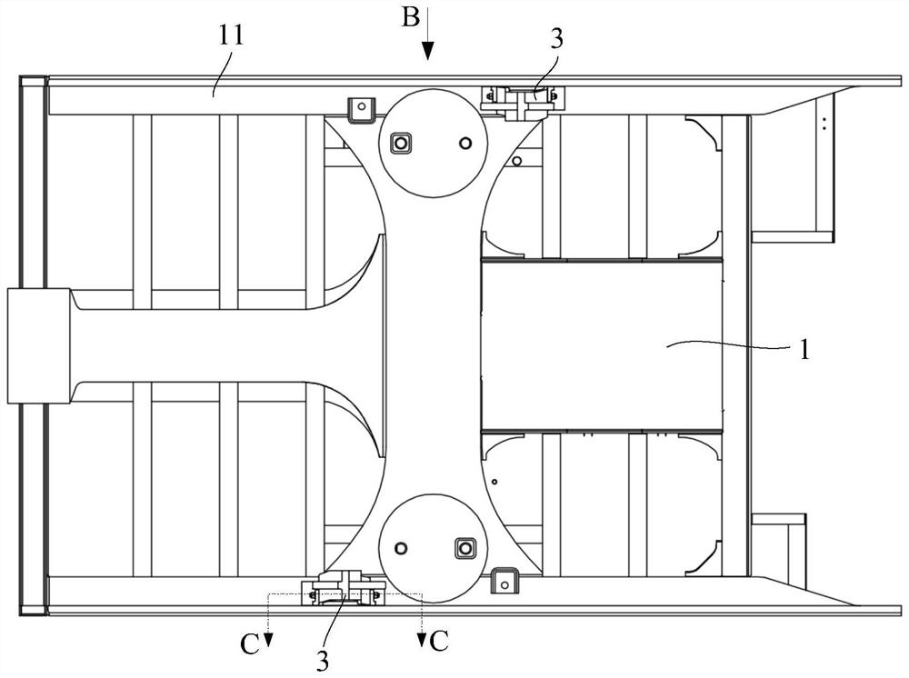
[0046] The embodiment of the present application also provides a car body 1, such as image 3 and Figure 4 As shown in the structure, the vehicle body 1 includes a side beam 11 , and also includes any tie rod seat 3 as provided in the above embodiments, and the base 31 of the tie rod seat 3 is fixedly connected to the side beam 11 . The car body 1 can be an end chassis part, and the side beam 11 bottom of the end chassis is equipped with a tie rod seat 3, such as Figure 5 , Figure 6 and Figure 7 As shown in the structure, the tie rod seat 3 can be welded to the side beam 11 through the top surface of the base 31, so that the base 31 and the side beam 11 form an integrated structure, the bogie 2 is installed on the bottom of the vehicle body 1, and the tie rod 21 and the frame The body 22 is installed on the tie rod seat 3 to realize the installation of the bogie 2.
Embodiment 3
[0048] The embodiment of the present application also provides a rail vehicle. The rail vehicle includes a bogie 2 and a car body 1 as provided in the above embodiment. The tie rod 21 of the bogie 2 is fixedly connected to the connecting structure of the connecting seat 32, and the steering The frame body 22 of the frame 2 is movably connected to the connection structure; as Figure 7 As shown in the structure, the bogie 2 is installed on the bottom of the car body 1. The bogie 2 includes a tie rod 21 and a frame body 22. One end of the tie rod 21 is fixedly connected to the connecting seat 32 of the tie rod seat 3 through a bolt 331 and a nut 332. The frame body 22 One end of one end is movably connected with the connection base 32 through a pin shaft passing through the oblong hole 323 , and the pin shaft can slide up and down in the oblong hole 323 .
PUM
 Abstract
Description
Claims
Application Information
 - R&D
- Intellectual Property
- Life Sciences
- Materials
- Tech Scout
- Unparalleled Data Quality
- Higher Quality Content
- 60% Fewer Hallucinations
Browse by: Latest US Patents, China's latest patents, Technical Efficacy Thesaurus, Application Domain, Technology Topic, Popular Technical Reports.
© 2025 PatSnap. All rights reserved.Legal|Privacy policy|Modern Slavery Act Transparency Statement|Sitemap|About US| Contact US: help@patsnap.com