IGBT junction temperature measuring method and device

A measurement method and a technology of a measurement device, which are applied in the direction of measurement devices, measurement of electrical variables, measurement of electricity, etc., can solve the problems of high precision requirements of measurement equipment, affecting the normal operation of IGBT devices, etc., and achieve the effect of accurate measurement results

Active Publication Date: 2020-06-02
GUANGDONG CHUTIAN DRAGON SMART CARD
View PDF6 Cites 2 Cited by
  • Summary
  • Abstract
  • Description
  • Claims
  • Application Information

AI Technical Summary

Problems solved by technology

[0005] In view of the above-mentioned defects or deficiencies in the prior art, it is desired to provide a method and device for measuring the junction temperature of the IGBT, which can solve the problems caused by the need to accurately obtain the load current val

Method used


Image

  • IGBT junction temperature measuring method and device
  • IGBT junction temperature measuring method and device
  • IGBT junction temperature measuring method and device

Examples


Embodiment Construction

[0023] The application will be further described in detail below in conjunction with the accompanying drawings and embodiments. It should be understood that the specific embodiments described here are only used to explain related inventions, rather than to limit the invention. It should also be noted that, for ease of description, only parts related to the invention are shown in the drawings.

[0024] It should be noted that, in the case of no conflict, the embodiments in the present application and the features in the embodiments can be combined with each other. The present application will be described in detail below with reference to the accompanying drawings and embodiments.

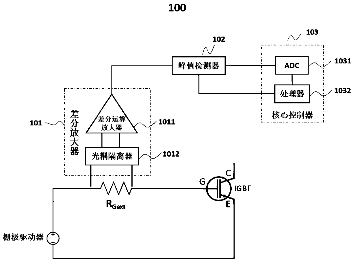
[0025] figure 1 It is a schematic structural diagram of an IGBT junction temperature measuring device in an embodiment of the present application. Such as figure 1 As shown, an IGBT junction temperature measurement device 100 includes but not limited to a differential amplifier 101 , a peak dete...


PUM


Abstract

An IGBT junction temperature measurement method comprises the steps: establishing a resistance-junction temperature corresponding model, wherein the resistance-junction temperature corresponding modelestablishes a corresponding relation between equivalent resistance in a grid electrode and IGBT junction temperature; obtaining grid external driving resistor RGext, grid turn-off voltage VGneg, a peak voltage drop VRGext _ peak at two ends of the grid external driving resistor, and a grid turn-on voltage VGpos; based on the grid external driving resistor RGext, the grid turn-on voltage VGpos, the grid turn-off voltage VGneg and the peak voltage drop VRGext _ peak at the two ends of the grid external driving resistor, calculating equivalent resistance RGint in the grid; and by combining the resistance-junction temperature corresponding model, obtaining the junction temperature of the IGBT. The method disclosed by the invention can solve the problem that a load current value needs to be accurately obtained or normal operation of an IGBT device is influenced when the IGBT junction temperature is measured by adopting a temperature-sensitive electrical parameter method in the prior art. The invention further correspondingly discloses an IGBT junction temperature measuring device.

Description

technical field [0001] The present application generally relates to the technical field of power electronic device detection, and specifically relates to a method and device for measuring the junction temperature of an IGBT. Background technique [0002] The junction temperature of the IGBT power device is one of the key parameters that affect the performance and reliability of the power converter device. Knowing the junction temperature information of the power device during the operation of the power system and monitoring the working status of the power device in real time are crucial to improving the service life of the power module and ensuring the power The safe and reliable operation of the system is of great significance. [0003] Conventional IGBT power device junction temperature detection methods can be divided into three categories: physical contact method, optical method and temperature-sensitive electrical parameter method. The physical contact method generally...

Claims


Application Information

Patent Timeline
IPC IPC(8): G01R31/26
CPCG01R31/2619
Inventor 邬亮童乔凌江佳闵闰陈晓飞张烨其他发明人请求不公开姓名
Owner GUANGDONG CHUTIAN DRAGON SMART CARD
Why Eureka
Try Eureka