Small and medium-sized navigation channel bridge monitoring device

A monitoring device, small and medium-sized technology, applied in traffic control systems, televisions, instruments, etc., can solve the problems of high cost and infeasibility of small and medium-sized bridges, and achieve the effect of reducing cost, reducing requirements, and increasing possibilities

Active Publication Date: 2020-06-02
TONGJI UNIV
View PDF8 Cites 9 Cited by
  • Summary
  • Abstract
  • Description
  • Claims
  • Application Information

AI Technical Summary

Problems solved by technology

VTS and AIS need to install a large number of expensive equipment, the cost is high and a rel

Method used


Image

  • Small and medium-sized navigation channel bridge monitoring device
  • Small and medium-sized navigation channel bridge monitoring device
  • Small and medium-sized navigation channel bridge monitoring device

Examples


Embodiment 1

[0030] In this embodiment, all small and medium-sized waterway bridge monitoring devices 100 (hereinafter referred to as bridge monitoring devices) are all communicated with a management server 200, so that the management server 200 can complete the data processing of the waterways monitored by each bridge monitoring device 100. collection, management or response.

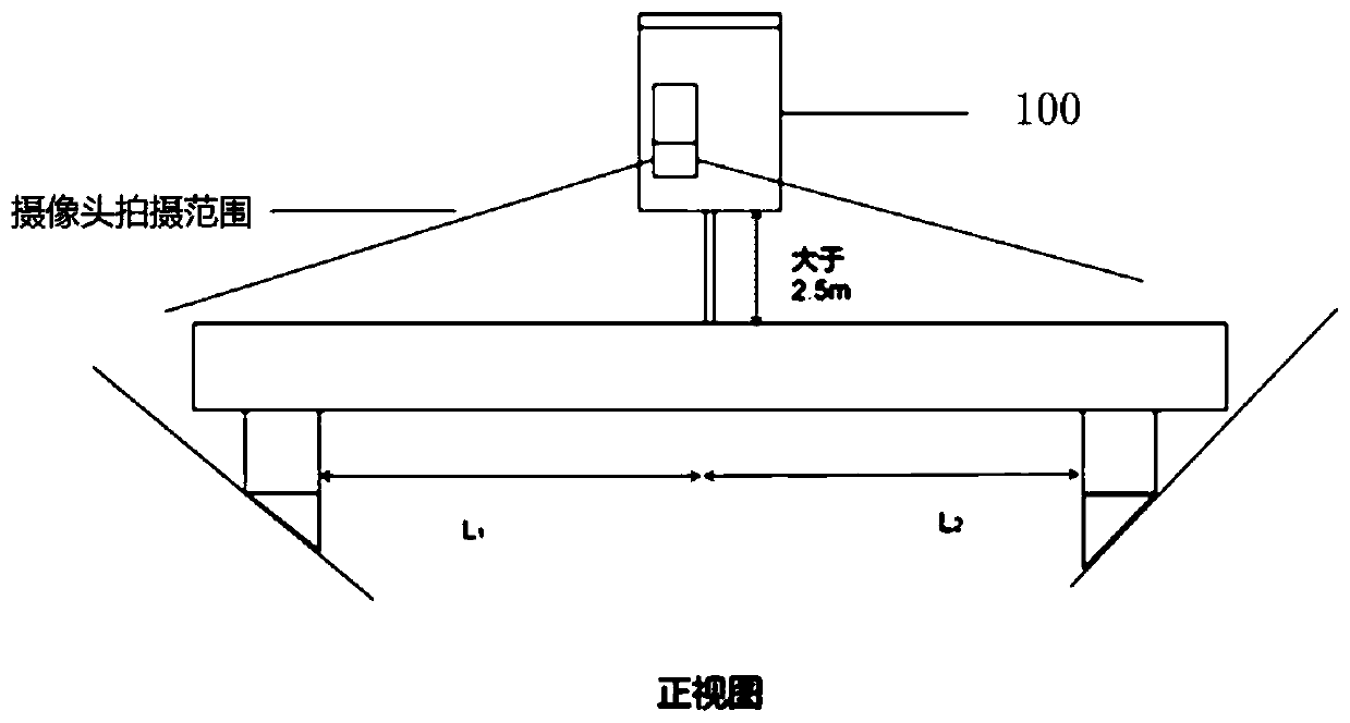
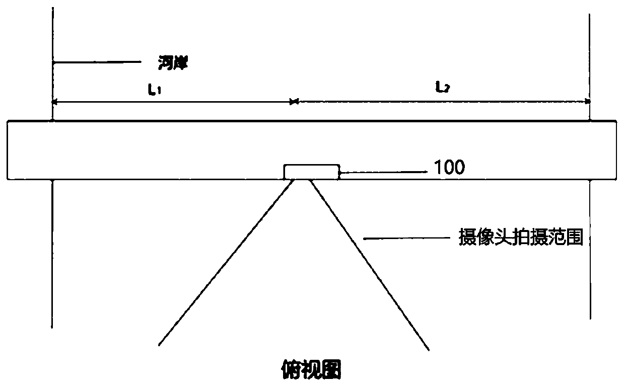
[0031] figure 1 It is a front view of the installation position of the bridge monitoring device in this embodiment, figure 2 It is a top view of the installation position of the bridge monitoring device in this embodiment.

[0032] Such as figure 1 , figure 2 As shown, the bridge monitoring device 100 is installed on the side of the bridge deck, so as to monitor the waterway at a position that does not affect the driving of the vehicle and the sight of the driver.

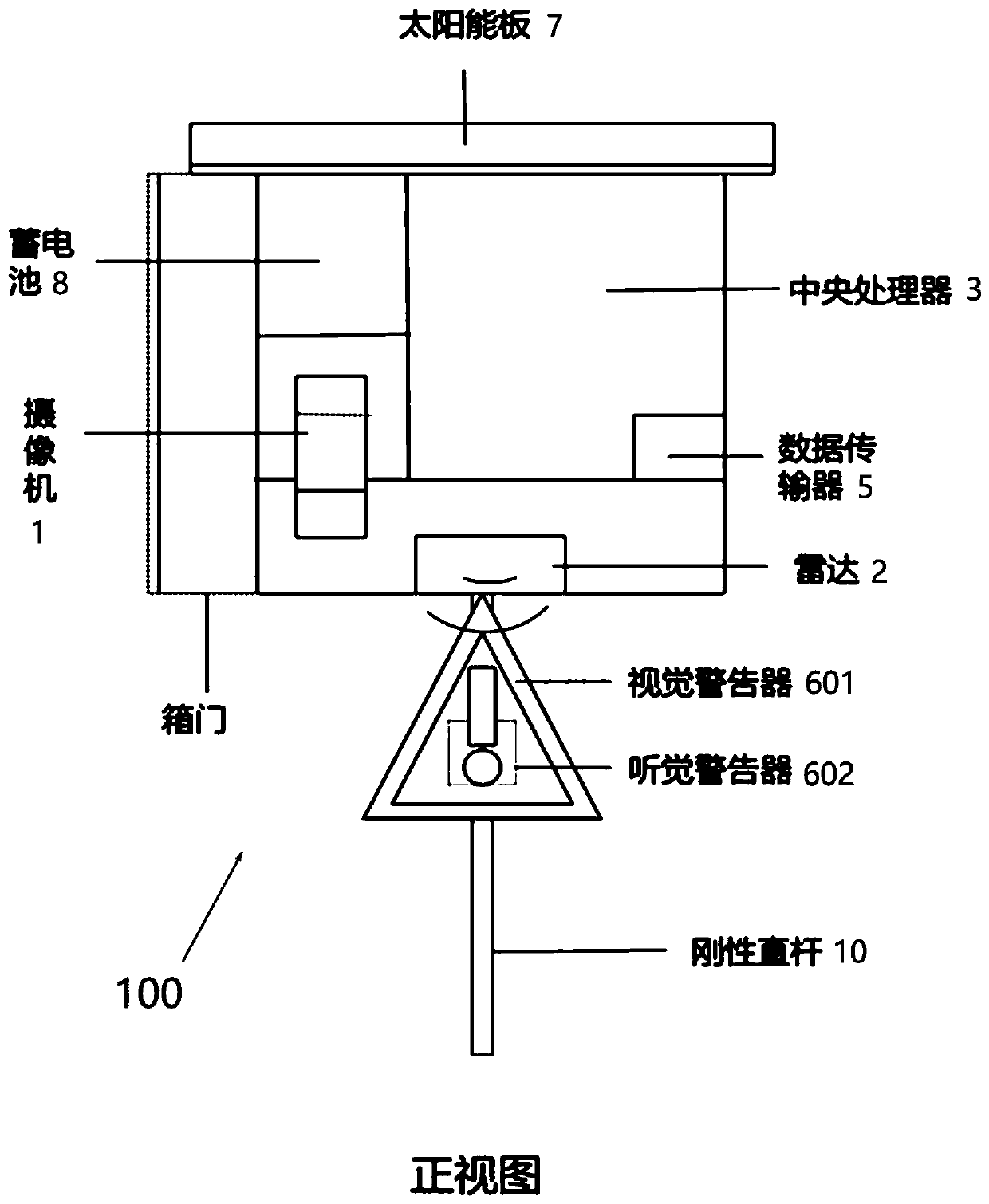
[0033] image 3 It is the structural front view of the bridge monitoring device in this embodiment, Figure 4 It is a structural side view of t...

Embodiment 2

[0148] In the second embodiment, the components having the same structure as those in the first embodiment are given the same symbols and corresponding explanations are omitted.

[0149] Figure 8 It is a stereoscopic view of the installation position of the bridge monitoring device in the second embodiment and Figure 9 It is a top view of the installation position of the bridge monitoring device in the second embodiment.

[0150] Compared with Example 1, as Figure 8 and Figure 9 As shown, the second embodiment adopts two bridge monitoring devices 200 and 300 respectively arranged on both sides of the river bank of the waterway. Therefore, when it is inconvenient to install the bridge monitoring device 100 on the bridge, or when it is impossible to capture a good channel water monitoring video on the bridge surface, the bridge monitoring devices 200 and 300 provided by the second embodiment can be used to monitor the channel.

[0151] In this embodiment, when the bridge...


PUM


Abstract

The invention provides a small and medium-sized navigation channel bridge monitoring device characterized in that the device is arranged on a small and medium-sized bridge and directly facing a navigation channel so as to monitor a ship target in the navigation channel, is arranged on the bridge and comprises a camera which is arranged on the small and medium-sized bridge, directly faces the center line of the navigation channel and is used for shooting the navigation channel so as to obtain a corresponding real-time monitoring video; a radar which is arranged on small and medium-sized bridgesand is at least used for continuously scanning the navigation channel and obtaining a real-time scanning position when a ship target is scanned; a warning module which is used for sending an acousto-optic warning to a ship target in the navigation channel; and a central processing unit in communication connection with the camera, the radar and the warning module, wherein the central processing unit comprises a neural network model storage part, a monitoring information acquisition cache part, a ship target identification part, a video coordinate conversion part, a radar coordinate conversionpart, a data fusion part, a track information identification part, a track prediction part and an early warning analysis output part.

Description

technical field [0001] The invention belongs to the field of structural safety and navigation safety monitoring, and in particular relates to a bridge monitoring system integrated with medium and small waterways based on the fusion of video and radar (photoelectricity). Background technique [0002] The ship collision accident has a great impact on the safe transportation of bridges and roads, people's life and property, and even the development of social economy. With the continuous economic growth and the increasing demand for transportation facilities, the number of bridges in my country is constantly increasing. The construction of bridges can relieve traffic pressure and promote land transportation. However, for water ships, bridges are artificial obstacles. When ships sail under the bridge, there is a danger of colliding with bridge piers or bridge span structures, which poses a threat to the safety of bridges and ships, and at the same time poses a threat to the safet...

Claims


Application Information

Patent Timeline
IPC IPC(8): H04N7/18G08G3/00G08G3/02G06K9/00
CPCH04N7/181G08G3/00G08G3/02G06V20/00
Inventor 马海英邵珠峰夏烨王君杰孙利民
Owner TONGJI UNIV
Why Eureka
Try Eureka