Hollow tube forming technology
A forming process and hollow tube technology, applied in metal rolling and other directions, can solve the problem of high defective rate of hollow balls, achieve fast coating operation and reduce defective rate
- Summary
- Abstract
- Description
- Claims
- Application Information
AI Technical Summary
Benefits of technology
Problems solved by technology
Method used
Image

Examples
Embodiment 1
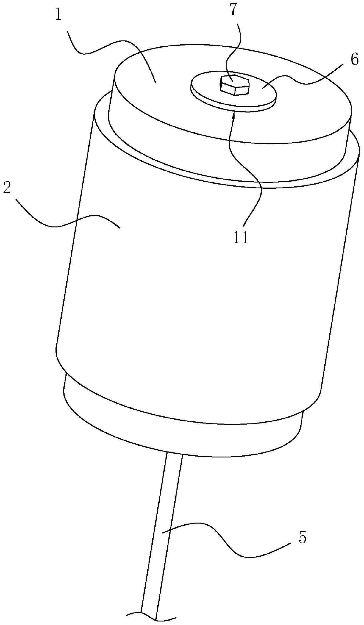
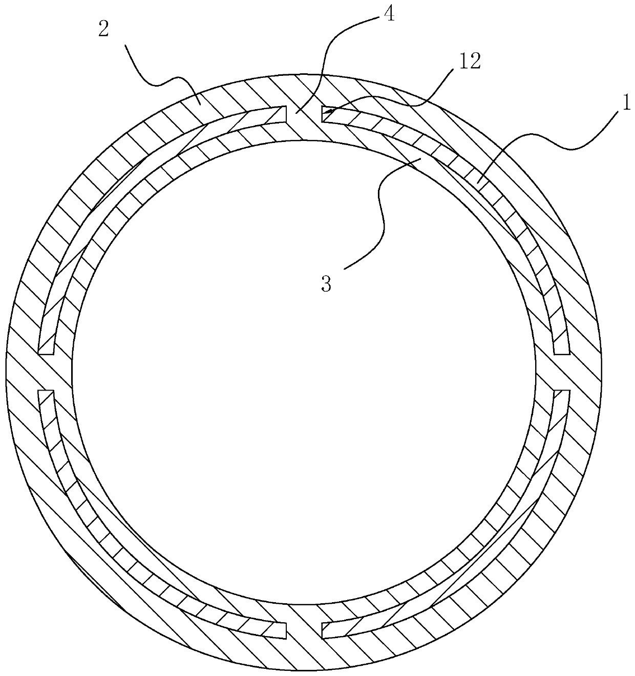
[0035] Embodiment one: a kind of coating device for coating lubricating liquid, refer to the attached figure 1 And attached figure 2 , including a cylinder 1 with a hollow interior, a coating sleeve 2 sleeved outside the housing 1 , an absorbing sleeve 3 inside the housing 1 , and a drawstring 5 fixedly connected to one end of the housing 1 . The outer side of the housing tube 1 is provided with a number of relief holes 12 evenly distributed around the axis of the housing cylinder 1, and a connection block 4 is arranged in the relief hole 12, and the side of the connection block 4 close to the absorption sleeve 3 is fixedly connected with the absorption sleeve 3, The side of the connection block 4 close to the coating sleeve 2 is fixedly connected with the coating sleeve 2 . The coating sleeve 2, the connecting block 4 and the absorption sleeve 3 are all made of sponge material, and the outer diameter of the coating sleeve 2 is slightly larger than the inner diameter of the ...
Embodiment 2
[0038] Embodiment two: a hollow tube molding process, comprising the following steps:
[0039] a. Raw material melting: select raw materials with a gold content greater than or equal to 99.99%, and heat the raw materials to 1150°C to make the raw materials into a molten state;
[0040] b. Pouring cylindrical billet: inject molten raw material into the casting mold for molding, after pouring is completed, cool the raw material to room temperature naturally, and then take out the formed cylindrical billet from the mold;
[0041] c. Billet heating: place the cylindrical billet in the heating furnace for heating, heat the cylindrical billet to 900°C, after heating to the specified temperature, keep the cylindrical billet in the heating furnace for 600s, after the heat preservation is completed, take the billet out of the heating furnace; During the heating process, a walking heating furnace is used for heating;
[0042]d. Piercing and rolling: After the billet is taken out of...
Embodiment 3
[0048] Embodiment three: a hollow tube molding process, comprising the following steps:
[0049] a. Raw material melting: select raw materials with a gold content greater than or equal to 99.99%, and heat the raw materials to 1175°C to make the raw materials into a molten state;
[0050] b. Pouring cylindrical billet: inject molten raw material into the casting mold for molding, after pouring is completed, cool the raw material to room temperature naturally, and then take out the formed cylindrical billet from the mold;
[0051] c. Billet heating: place the cylindrical billet in the heating furnace for heating, heat the cylindrical billet to 925°C, after heating to the specified temperature, keep the cylindrical billet in the heating furnace for 800s, after the heat preservation is completed, take the billet out of the heating furnace; During the heating process, a walking heating furnace is used for heating;
[0052] d. Piercing and rolling: After the billet is taken out...
PUM
 Abstract
Description
Claims
Application Information
 - R&D Engineer
- R&D Manager
- IP Professional
- Industry Leading Data Capabilities
- Powerful AI technology
- Patent DNA Extraction
Browse by: Latest US Patents, China's latest patents, Technical Efficacy Thesaurus, Application Domain, Technology Topic.
© 2024 PatSnap. All rights reserved.Legal|Privacy policy|Modern Slavery Act Transparency Statement|Sitemap