GPU baffle mounting device

A technology for mounting devices and baffles, which is applied in the direction of workpiece clamping devices, hand-held tools, manufacturing tools, etc., can solve problems such as poor operation of GPUs, easy-to-touch and damaged components, and difficulty in maintaining the horizontal insertion of the mounting part 105, so as to reduce the Installation efficiency, stable and reliable sliding, and the effect of reducing costs and resources

Active Publication Date: 2020-06-05
INSPUR SUZHOU INTELLIGENT TECH CO LTD
View PDF6 Cites 0 Cited by
  • Summary
  • Abstract
  • Description
  • Claims
  • Application Information

AI Technical Summary

Problems solved by technology

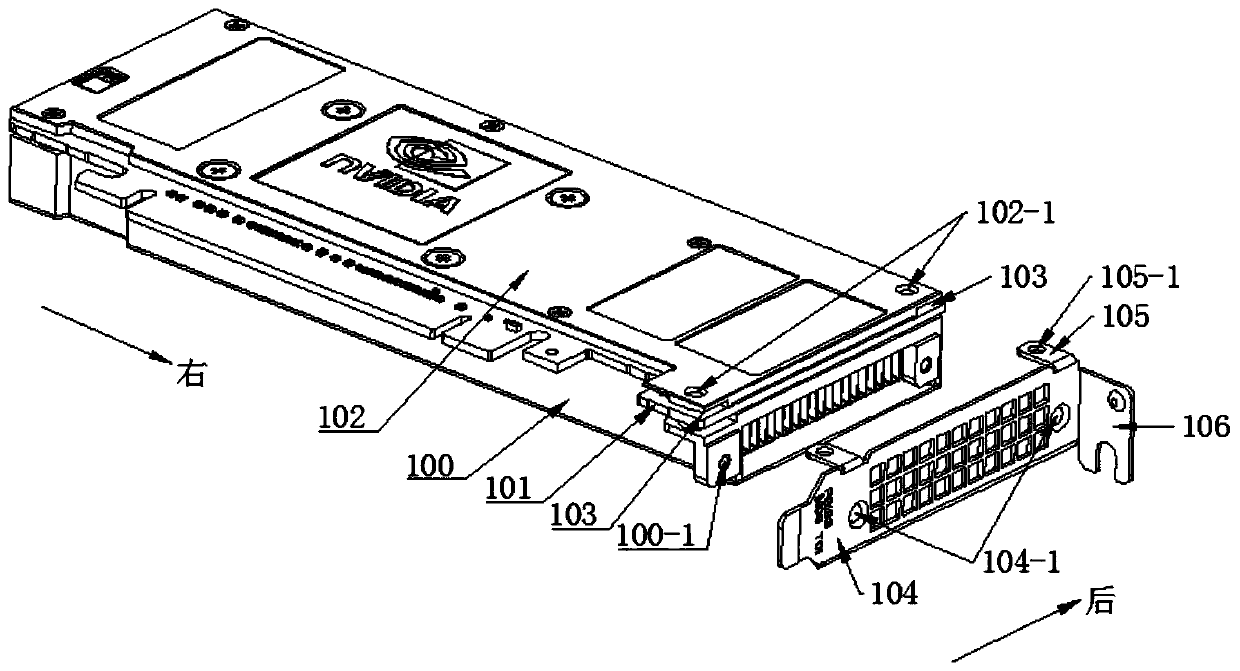
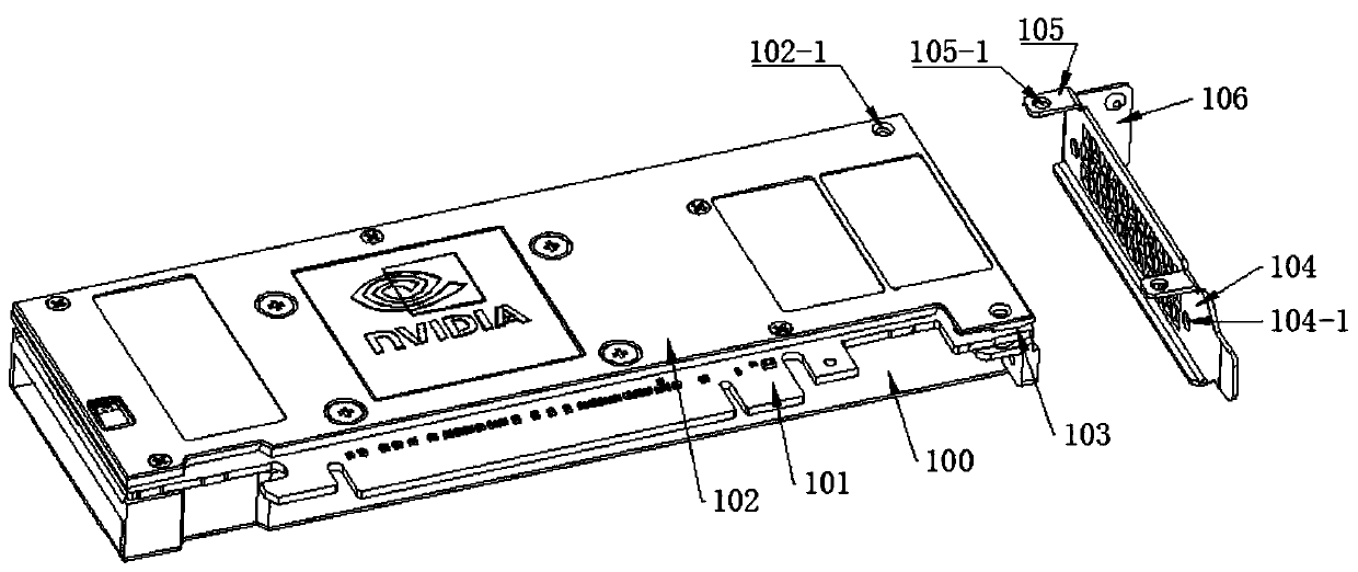
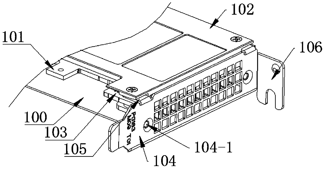
[0004] When the operator holds the blocking piece and inserts the mounting portion 105 of the blocking piece into the installation groove 103, it is difficult for the operator to maintain the horizontal insertion of the mounting portion 105 into the mounting groove 103 due to factors such as working conditions and viewing angles. The mounting part 105 is inserted into the mounting groove 103 inclined downwards, and it is easy to damage the components located on the upper end surface of the GPU circuit board 101, thereby causing poor operation of the GPU.

Method used


Image

  • GPU baffle mounting device
  • GPU baffle mounting device
  • GPU baffle mounting device

Examples


Embodiment 1

[0050] A GPU block installation device includes a bottom plate 1, a GPU fixing component, and a block fixing component.

[0051] Such as Figure 4 As shown, the GPU fixing assembly includes a first GPU fixing seat 2-1 and a second GPU fixing seat 2-2. The first GPU fixed seat 2-1 and the second GPU fixed seat 2-2 are welded and fixed on the upper end surface of the base plate 1, the first GPU fixed seat 2-1 is located at the left end of the base plate 1, and the second GPU fixed seat 2-2 is located at the left end of the base plate 1. In the middle of the base plate 1, two first GPU fixing seats 2-1 and second GPU fixing seats 2-2 are arranged side by side, and the upper end surface of the first GPU fixing seat 2-1 is provided with a first GPU fixing groove 2- 1-1, the upper end surface of the second GPU fixing seat 2-2 is provided with a second GPU fixing slot 2-2-1.

[0052] Such as Figure 4 As shown, the upper end surface of the bottom plate 1 is provided with a sliding...

Embodiment 2

[0066] In step (4) of Embodiment 1, because the operator uses the electric screwdriver manually, once the operator's hand is unstable, the electric screwdriver will be skewed, so that the electric screwdriver will be skewed together with the second fastener, When the second fastener is screwed into the GPU circuit board mounting hole of the GPU circuit board 101 , it is easy to scratch the edge of the GPU circuit board mounting hole and cause damage to the GPU circuit board 101 , hindering the normal operation of the GPU.

[0067] For this, if Figure 8 As shown, in a GPU block installation device of Embodiment 2, a guide plate 7 is provided on the upper end surface of the first block fixing seat 6-1, as Figure 9 As shown, the guide plate 7 is hinged with the first flap holder 6-1 through the hinge 8, as Figure 10 As shown, the guide plate 7 is provided with a second fastener guide hole 7-1.

[0068] Such as Figure 8 with 11 As shown in and 12, the second fastener guide...


PUM


Abstract

The invention discloses a GPU baffle mounting device and relates to the technical field of GPU baffle mounting. The GPU baffle mounting device comprises a bottom plate, a GPU fixing assembly and a baffle fixing assembly, wherein the lower end of the GPU fixing assembly is connected with the bottom plate, the baffle fixing assembly comprises a first baffle fixing seat and a second baffle fixing seat, the first baffle fixing seat is in sliding connection with the bottom plate, one side, close to the GPU fixing assembly, of the first baffle fixing seat is provided with the second baffle fixing seat, and the upper end surface of the second baffle fixing seat is provided with a baffle body fixing groove used for being matched with a baffle body of a baffle. The GPU baffle mounting device can keep mounting parts of the baffle horizontally inserted into mounting grooves in the process of mounting the baffle.

Description

technical field [0001] The present invention relates to the technical field of GPU block installation, in particular to a GPU block installation device. Background technique [0002] Such as Figure 1-3 As shown, the GPU includes a GPU shield 102 , a GPU circuit board 101 , a GPU body 100 , and a block. The GPU shield 102 , the GPU circuit board 101 , and the GPU body 100 are fixed together by screws sequentially from top to bottom. The baffle is arranged on one side of the body of the GPU, and the baffle includes a baffle body 104, a mounting portion 105, and a bending portion 106. The mounting portion 105 is formed by bending the upper end of the baffle body 104 toward the GPU body 100, The bent portion 106 is formed by bending the rear end of the block body 104 in a direction away from the GPU body 100 . [0003] When installing the baffle, the operator first holds the baffle and brings the baffle close to the GPU body 100, so that the installation part 105 is horizonta...

Claims


Application Information

Patent Timeline
Patent Type & Authority Applications(China)
IPC IPC(8): B25B27/14B25B11/02
CPCB25B11/02B25B27/14
Inventor 刘伟徐建强
Owner INSPUR SUZHOU INTELLIGENT TECH CO LTD
Why Eureka
Try Eureka