
Modularized railway vehicle body

A rail vehicle and modular technology, applied in the field of rail vehicles, can solve the problems of not providing window height, various tooling, and poor appearance visibility, so as to promote unified and modular design, reduce life cycle costs, and improve The effect of product competitiveness

Active Publication Date: 2020-06-05
ZHUZHOU ELECTRIC LOCOMOTIVE CO
View PDF14 Cites 26 Cited by
  • Summary
  • Abstract
  • Description
  • Claims
  • Application Information

AI Technical Summary

Problems solved by technology

However, this patent scheme does not provide a general idea of ​​equipment installation, nor does it explain the simplified scheme of the height and length of the car body, and the operability is not high.
[0005] Chinese patent CN201520819504.6 relates to the modular side wall structure of the train car body. This solution focuses on solving the stress concentration problem caused by avoiding the weld line at the corner of the window, but does not provide some travel routes that require the height of the window to be increased. The solution to structural problems cannot meet the needs of more users
[0006] Chinese patent CN201520190079 provides a modular car body suitable for various boundaries. This patent only proposes a unified concept from the perspective of the outer contour limit of the car body, and does not provide a specific car body structure implementation plan
[0007] In addition, due to the needs of vehicle transportation, binding and fixing, vehicle transfer, etc., many projects have set up special structures such as croissant, semicircular, and U-shaped under the side beams of the chassis, resulting in complex vehicle body structure, various tooling, high cost, and visible appearance. Poor performance, and these additional structures are prone to interference with bogies and other equipment

Method used


Image

  • Modularized railway vehicle body
  • Modularized railway vehicle body
  • Modularized railway vehicle body

Examples


Embodiment Construction

[0071] The present invention will be described in detail below with reference to the accompanying drawings and examples. It should be noted that, in the case of no conflict, the embodiments of the present invention and the features in the embodiments can be combined with each other. For the convenience of description, if the words "up", "down", "left" and "right" appear in the following, it only means that the directions of up, down, left and right are consistent with the drawings themselves, and do not limit the structure.

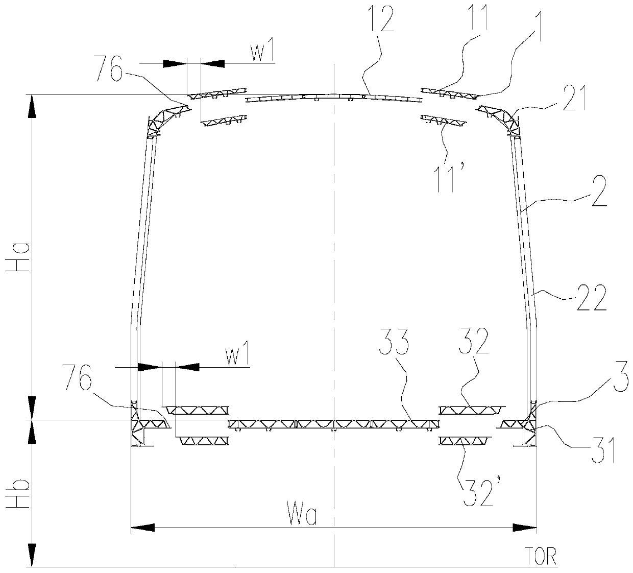
[0072] A modular subway (take the subway train body as an example) car body, such as figure 1 Shown: the vehicle body comprises a roof 1, a side wall 2, an underframe 3, an end wall 4 and a driver's cab framework 5. The roof 1 adopts a long micro-arc roof structure. The side wall 2 adopts an integral structure, and is composed of a side wall top profile 21 with a long upper part and a block side wall unit 22 . For the domestic A / B type subway car, the ...


PUM


Abstract

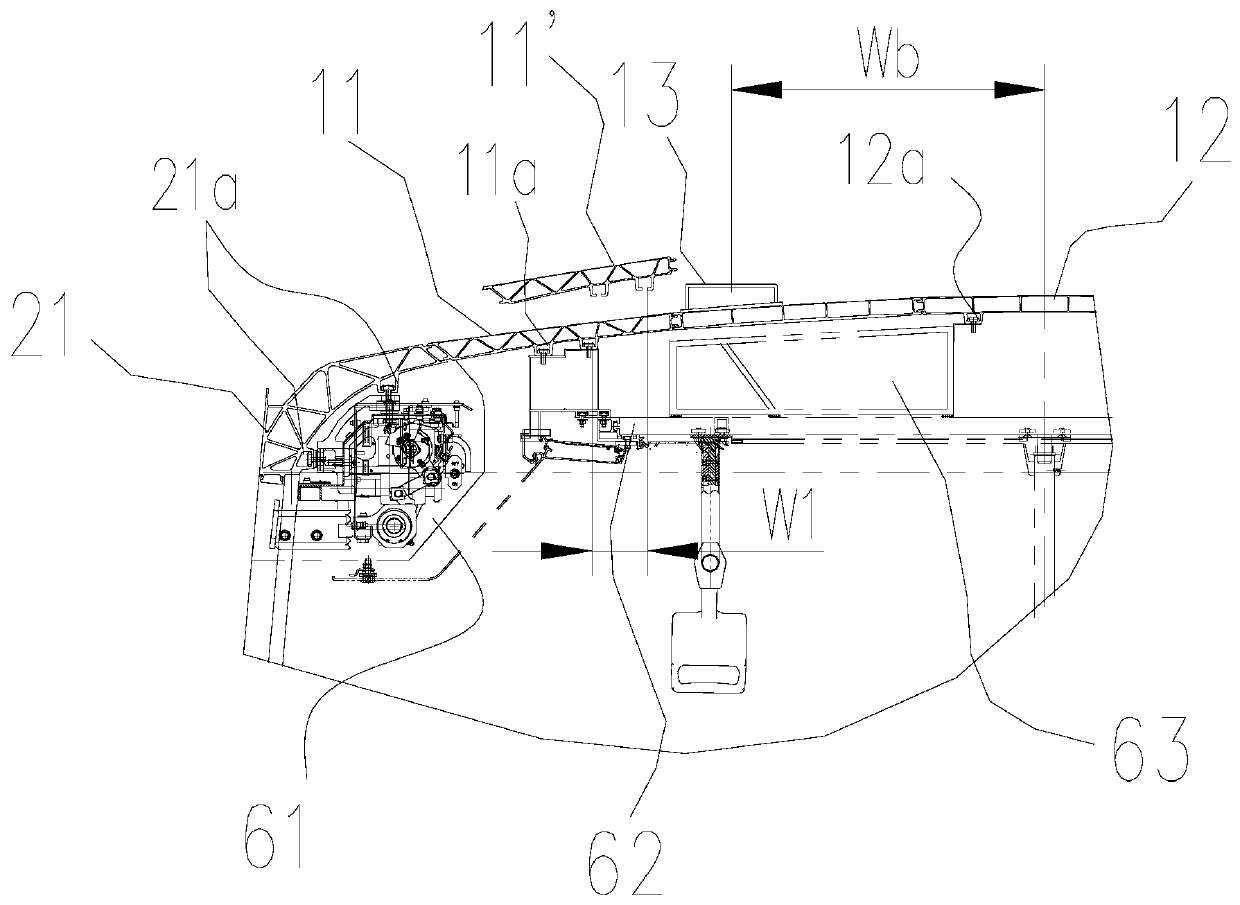
The invention discloses a modular railway vehicle body. The vehicle body comprises a vehicle roof, side walls, a bottom frame, end walls and a cab framework. The roof adopts a full-length arc roof structure; the side wall is of an integral structure or a split structure, and the side wall is mainly composed of a side wall top profile and a plurality of side wall units. Each side wall unit is formed by assembling and welding a plurality of parallel door stand columns and side wall plate sectional materials, and the extending directions of the door stand columns and the side wall plate sectionalmaterials are perpendicular to the side wall top sectional materials. The bottom frame is mainly composed of bottom frame edge beams, floor middle profiles, sleeper beams, traction beams and anti-side-rolling installation bases. The roof and the side walls, the underframe edge beams and the floor edge section bars, and the floor edge section bars and the floor middle section bars are connected through lap joints or butt joint joints. According to the vehicle body, through the design of the top layer, the vehicle body structure and the section bar section are optimized, and the universality and the sharing rate are improved.

Description

technical field [0001] The invention relates to a modular rail vehicle body, which belongs to the technical field of rail vehicles, in particular to a subway train body structure. Background technique [0002] At present, the A / B type subway cars in China account for about 80% of the urban rail transit vehicles of various standards. Although the main outline dimensions of the A / B type subway cars are basically the same, the cross-section types are mainly drum-shaped, straight, and trapezoidal. However, due to the large differences in the technical systems of domestic manufacturers, the different installation interfaces of suppliers' equipment, and the more or less individual needs of users, there are hundreds of types of domestic subway train bodies. Too many types bring huge design, manufacturing and procurement costs to vehicle manufacturers, and also bring huge costs to vehicle users for spare parts procurement, storage and vehicle maintenance. The existence of these phe...

Claims


Application Information

Patent Timeline
IPC IPC(8): B61D17/04B61D17/12B61D17/06B61D17/08
CPCB61D17/045B61D17/048B61D17/12B61D17/06B61D17/08Y02T30/00
Inventor 柳晓峰金希红苏柯刘永强梁红波陈希王海钧水文菲廖文洁朱卫
Owner ZHUZHOU ELECTRIC LOCOMOTIVE CO
Learn More