
Synchronous adjusting device for multiple spacing and angles and implementation method of synchronous adjusting device

A synchronous adjustment and angle technology, applied in the field of multi-spacing angle synchronous adjustment devices, can solve problems such as inability to rotate, and achieve the effect of ensuring accuracy, improving efficiency and range of use

Pending Publication Date: 2020-06-05
ZHEJIANG DONGYANG CHENGJI ELECTRO MECHANICS CO LTD
View PDF0 Cites 1 Cited by
  • Summary
  • Abstract
  • Description
  • Claims
  • Application Information

AI Technical Summary

Problems solved by technology

The existing spacing adjustment devices on the market can only change the distance of multiple products at the same time, and cannot rotate the angle while changing the spacing

Method used


Image

  • Synchronous adjusting device for multiple spacing and angles and implementation method of synchronous adjusting device
  • Synchronous adjusting device for multiple spacing and angles and implementation method of synchronous adjusting device
  • Synchronous adjusting device for multiple spacing and angles and implementation method of synchronous adjusting device

Examples


Embodiment 1

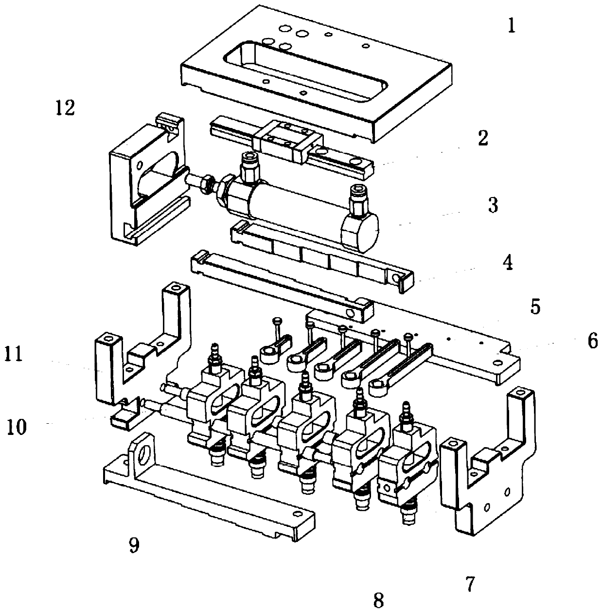
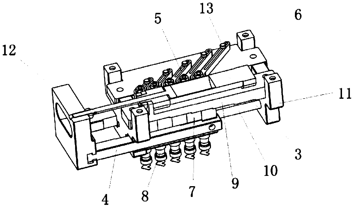
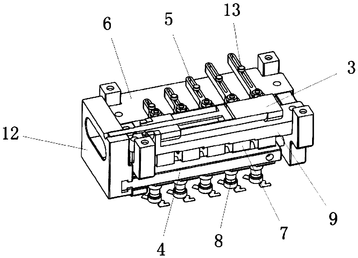
[0038] see Figure 1-8 , the present invention provides the following technical solutions: a multi-pitch angle synchronous adjustment device, including two sealing plates 11, a guide post 10 is connected between the two sealing plates 11, five sliders 7 are slidably connected to the guide post 10, The slider 7 is rotatably connected with a vacuum suction rod 8, and a displacement plate 6 is also connected between the two sealing plates 11. The displacement plate 6 is slidably connected with a rocker arm 5 corresponding to the slider 7. The other end is connected with the top of the vacuum suction rod 8, the two sides of the slider 7 are respectively connected with the push rod 4, the right end of the push rod 4 is connected with the slider 7 on the right side, and the first card is respectively opened on both sides of the slider 7. slot 71, and the depth of the first card slot 71 on the slider 7 increases sequentially from right to left, and the push rod 4 is provided with a f...

Embodiment 2

[0048]The difference between this embodiment and Embodiment 1 is that further, the length of the rocker arm 5 decreases successively from right to left, and the inside of the rocker arm 5 is provided with a chute 51, and the rocker arm 5 is connected to the displacement position through the positioning shaft 13. On the plate 6, and the end of the positioning shaft 13 passes through the chute 51 and is connected to the displacement plate 6.

[0049] Further, the positioning rotating shaft 13 is distributed obliquely on the displacement plate 6 , and the distance from the positioning rotating shaft 13 to the corresponding vacuum suction rod 8 decreases successively from right to left.

[0050] Further, the upper end of the vacuum suction rod 8 is provided with a limiting groove 81 , and the end of the rocker arm 5 is provided with a limiting sleeve 52 , and the limiting sleeve 52 is sleeved on the limiting groove 81 .

[0051] By adopting the above technical solution, the moveme...


PUM


Abstract

The invention discloses a synchronous adjusting device for multiple spacing and angles. The device comprises two sealing plates, a guiding column is connected between the two sealing plates, a plurality of sliding blocks are connected to the guiding column in a sliding mode, vacuum suction rods are rotationally connected to the sliding blocks, a position changing plate is further connected betweenthe two sealing plates, rocker arms corresponding to the sliding blocks are connected to the position changing plate in a sliding mode, pushing rods are connected to the two sides of the sliding blocks correspondingly, the right ends of the pushing rods are connected with the sliding blocks on the right side, a pushing plate fixing plate is connected to the left ends of the pushing rods, and an air cylinder is arranged on the upper ends of the sealing plates. The invention further discloses an implementation method of the synchronous adjusting device for the multiple spacing and angles. According to the device and the method, the air cylinder acts to drive the pushing plate fixing plate to act so as to drive the pushing rods to act, and the sliding blocks are driven to act under the cooperation of first clamping positions and first clamping grooves, so that spacing changing is achieved; and the rocker arms are arranged, and the sliding blocks act to drive the rocker arms to act so asto drive the vacuum suction rods to rotate, so that angle adjusting is achieved.

Description

technical field [0001] The invention belongs to the technical field of pitch adjustment, and in particular relates to a multi-pitch angle synchronous adjustment device and a realization method thereof. Background technique [0002] As one of the most important parts of automated handling, robotic suction cup gripping has undergone tremendous changes in just a few years. In recent years, customers are not only satisfied with the increase in the number of grips, but also can adjust the pitch and angle at the same time, so the multi-pitch angle synchronous adjustment technology came into being. The existing spacing adjustment devices on the market can only realize the simultaneous change of the distance of multiple products, and cannot rotate the angle while changing the spacing. [0003] Therefore, there is an urgent need for a multi-pitch angle synchronous adjustment device, so that not only the distance of multiple products can be changed at the same time during the automat...

Claims


Application Information

Patent Timeline
IPC IPC(8): B65G47/91B25J15/06
CPCB25J15/0616B65G47/91B65G2207/08
Inventor 李韩冰何理军
Owner ZHEJIANG DONGYANG CHENGJI ELECTRO MECHANICS CO LTD
Learn More