Automatic feeding device and intelligent cutting equipment

An automatic feeding and feeding technology, applied in thin material handling, sending objects, transportation and packaging, etc., can solve the problems of inaccurate leather material conveying, cylinder easily stuck, unstable positioning, etc., to avoid later docking problems, The effect of improving the feeding accuracy and preventing the cylinder from being out of synchronization

Pending Publication Date: 2020-06-05
DONGGUAN EMMA CNC TECH CO LTD
View PDF0 Cites 2 Cited by
  • Summary
  • Abstract
  • Description
  • Claims
  • Application Information

AI Technical Summary

Problems solved by technology

[0002] The feeding method of the traditional leather feeding device is generally to install cylinders at both ends of the beam, and the beam is driven up and down by the cylinder so that the beam is pressed on the leather material, and the leather material is driven forward by the moving mechanism. This method is due to the movement of the cylinders at both ends. Out of sync or failure will easily lead to inconsistencies in the degree of compres

Method used


Image

  • Automatic feeding device and intelligent cutting equipment
  • Automatic feeding device and intelligent cutting equipment
  • Automatic feeding device and intelligent cutting equipment

Examples


Embodiment 1

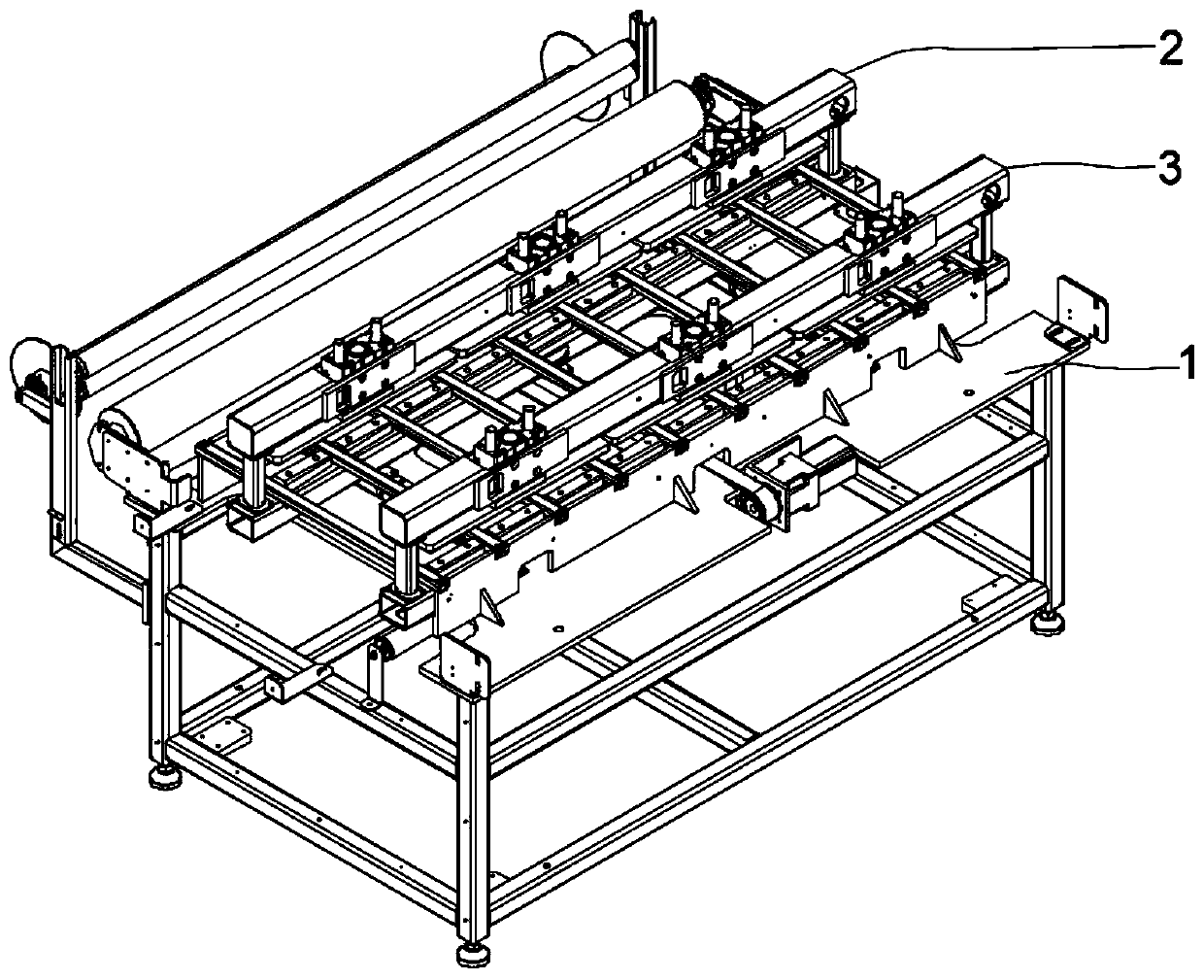
[0029] see Figure 1-4 As shown, the present invention relates to an automatic feeding device, including an installation platform 1, on which a movable pulling mechanism 2 and a fixed pressing mechanism 3 are arranged, and the movable pulling mechanism 2 moves on the installation platform 1 For feeding, the fixed pressing mechanism 3 is arranged behind the movable pulling mechanism 2 for positioning the pressing.

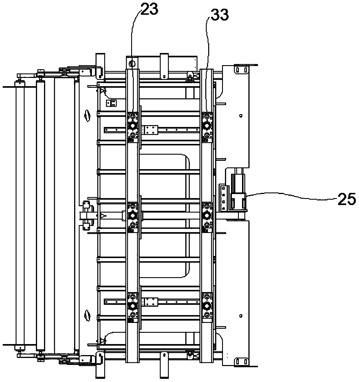
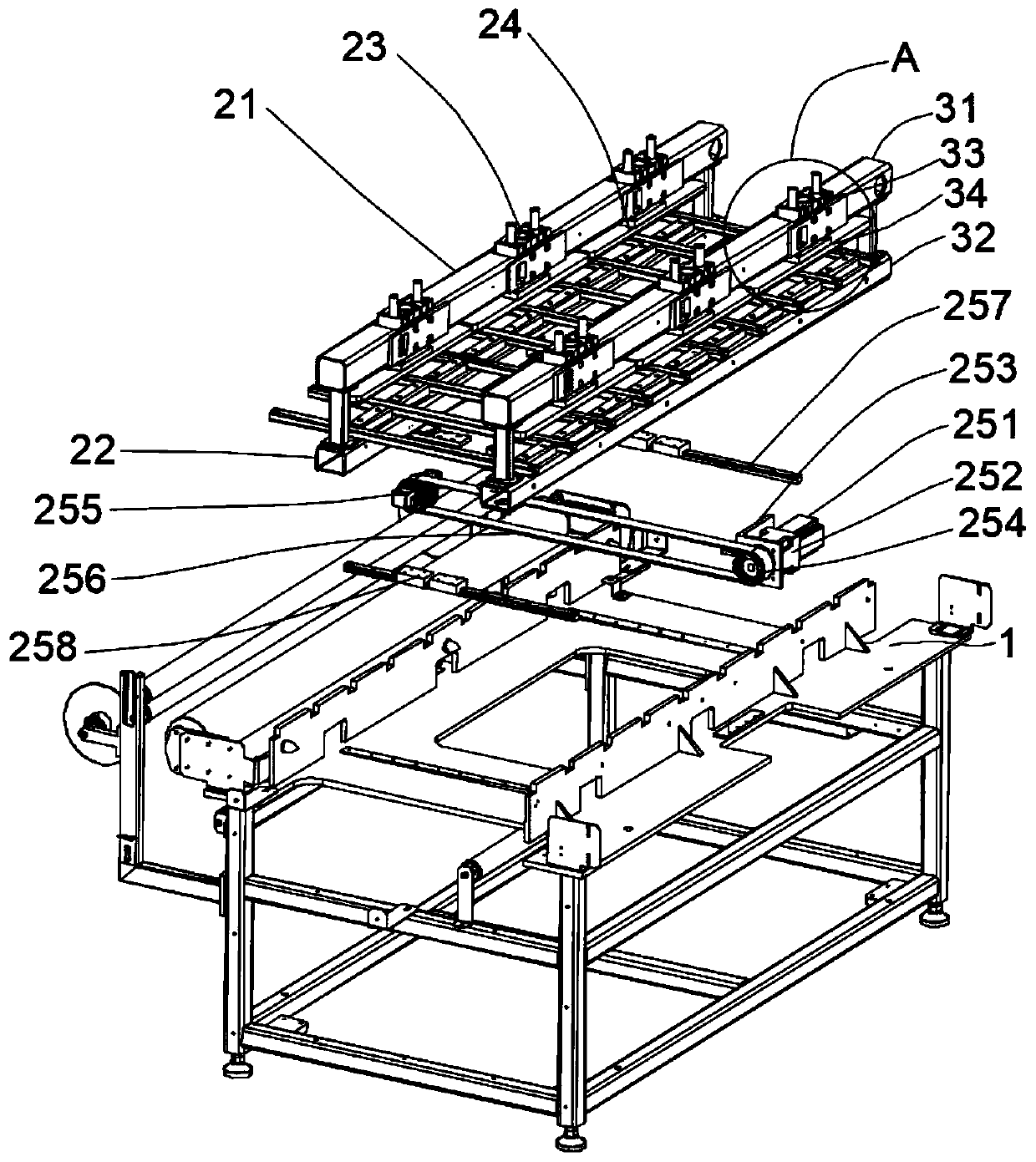
[0030] Preferably, the movable pulling mechanism 2 includes a first upper beam 21, a first lower beam 22, a first driving device 23, a first pressing plate 24 and a feeding driving mechanism 25, and the feeding driving mechanism 25 is arranged on the installation table 1 Above, the first lower beam 22 is set on the feeding drive mechanism 25, the first upper beam 21 is fixed on the first lower beam 22 through a connecting rod, and the first upper beam 21 is provided with three first driving Set 23, the first platen 24 is respectively connected under the three first...

Embodiment 2

[0034]This embodiment is a modification of Embodiment 1. The change is that: the feeding drive mechanism 25 is a screw transmission mechanism, including a servo motor 251, a reduction motor 252, a motor seat 253, a transmission screw, a screw nut, a connection Seat, straight line rail 257 and guide block 258, the transmission screw rod is arranged in the installation platform 1, the screw nut is set on the transmission screw rod, and the reduction motor 252 is arranged on the installation platform through the motor base 253 1 and is connected with the transmission screw, the servo motor 251 is connected with the reduction motor 252, the connecting seat is connected with the screw nut, two straight line rails 257 are respectively arranged on the installation platform 1, and two straight Guide blocks 258 are arranged on the line rails 257 respectively, and the first lower beam 22 is arranged on the guide blocks 258 and the connecting seat.

Embodiment 3

[0036] This embodiment is a variation example of Embodiment 1. The variation lies in that: the feeding drive mechanism 25 is a rack and pinion meshing transmission mechanism, including a servo motor 251, a reduction motor 252, a motor base 253, a transmission gear, a rack, a straight Profile rail 257 and guide block 258, the rack is slidably arranged on the mounting table 1, the transmission gear is meshed with the rack, and the reduction motor 252 is arranged on the mounting table 1 through the motor base 253 and is driven with the transmission gear. connected, the servo motor 251 is connected with the geared motor 252, the straight line rail 257 is set on the installation table 1, the guide block 258 is slid on the straight line track 257, and the first lower beam 22 is set On the guide block 258 and the rack.


PUM


Abstract

The invention relates to an automatic feeding device and intelligent cutting equipment. The automatic feeding device comprises a rack, wherein a movable material pulling mechanism and a fixed materialpressing mechanism are arranged on the rack; the movable material pulling mechanism is used for moving and feeding on the rack; the fixed material pressing mechanism is arranged behind the movable material pulling mechanism and used for positioning and pressing materials; first driving devices and first pressing plates are arranged on the movable material pulling mechanism; the first driving devices are in transmission connection with the first pressing plates; second driving devices and second pressing plates are arranged on the fixed material pressing mechanism; and the second driving devices are in transmission connection with the second pressing plates. According to the automatic feeding device, a first upper cross beam and a second upper cross beam are respectively provided with at least one pressing device, the pressing devices drive the pressing plates to move downwards to press the leather materials, and the problem that air cylinders are not synchronized is avoided; the feeding device and a cutting device of the intelligent cutting equipment are installed on the integrated rack so as to avoid the problem of later butt joint; and according to the automatic feeding device and the intelligent cutting equipment, the positioning and pulling stability of conveying the single-layer or multi-layer leather materials are effectively improved, and the feeding precision is improved.

Description

technical field [0001] The invention relates to the technical field of leather cutting, in particular to an automatic feeding device and its intelligent cutting equipment. Background technique [0002] The feeding method of the traditional leather feeding device is generally to install cylinders at both ends of the beam, and the beam is driven up and down by the cylinder so that the beam is pressed on the leather material, and the leather material is driven forward by the moving mechanism. This method is due to the movement of the cylinders at both ends. Out of sync or failure will easily lead to inconsistencies in the degree of compression on both sides of the leather material, causing problems such as inaccurate leather material transmission accuracy and easy jamming of the cylinder. [0003] In addition, the existing cutting equipment is provided with the feeding device and the cutting device separately, which is difficult to install during docking, cannot guarantee the d...

Claims


Application Information

Patent Timeline
IPC IPC(8): B65H35/06B65H20/16
CPCB65H20/16B65H35/06B65H2403/21B65H2403/41B65H2403/46B65H2701/178
Inventor 王炜棠陈永君
Owner DONGGUAN EMMA CNC TECH CO LTD
Why Eureka
Try Eureka