Bridge pile foundation pile head pouring connection steel bar structure and construction method thereof

A technology for connecting steel bars and bridges, which is applied in basic structure engineering, bridges, bridge construction, etc., can solve the problems of no steel bar support, void around the concrete pile head, and unreliable joints, so as to improve the joint strength and secure the joints Effect

Pending Publication Date: 2020-06-05
安徽建工路港建设集团有限公司
View PDF0 Cites 0 Cited by
  • Summary
  • Abstract
  • Description
  • Claims
  • Application Information

AI Technical Summary

Problems solved by technology

Since the general steel bars are linear, and are usually placed directly on the upper part of the concrete pile head or directly on the outer side of the circumference, the steel bar frame of the bridge is bound to the steel bars on or around the concrete pile head. , so that the surrounding area of ​​the concrete pile head is empty, and there is no tight steel support (see attached Figure 8 ), it is easy to make the connection between the main body of the bridge and the concrete pile head unstable, and it is easy to cause the connection between the main body of the bridge and the foundation through the pouring column to be unreliable in the later stage, and there are potential safety hazards, which need to be improved urgently

Method used


Image

  • Bridge pile foundation pile head pouring connection steel bar structure and construction method thereof
  • Bridge pile foundation pile head pouring connection steel bar structure and construction method thereof
  • Bridge pile foundation pile head pouring connection steel bar structure and construction method thereof

Examples


Embodiment Construction

[0042] In order to make the purpose, technical solutions and advantages of the embodiments of the present invention clearer, the technical solutions in the embodiments of the present invention will be clearly and completely described below in conjunction with the embodiments of the present invention. Obviously, the described embodiments are part of the present invention Examples, not all examples. Based on the embodiments of the present invention, all other embodiments obtained by persons of ordinary skill in the art without creative efforts fall within the protection scope of the present invention.

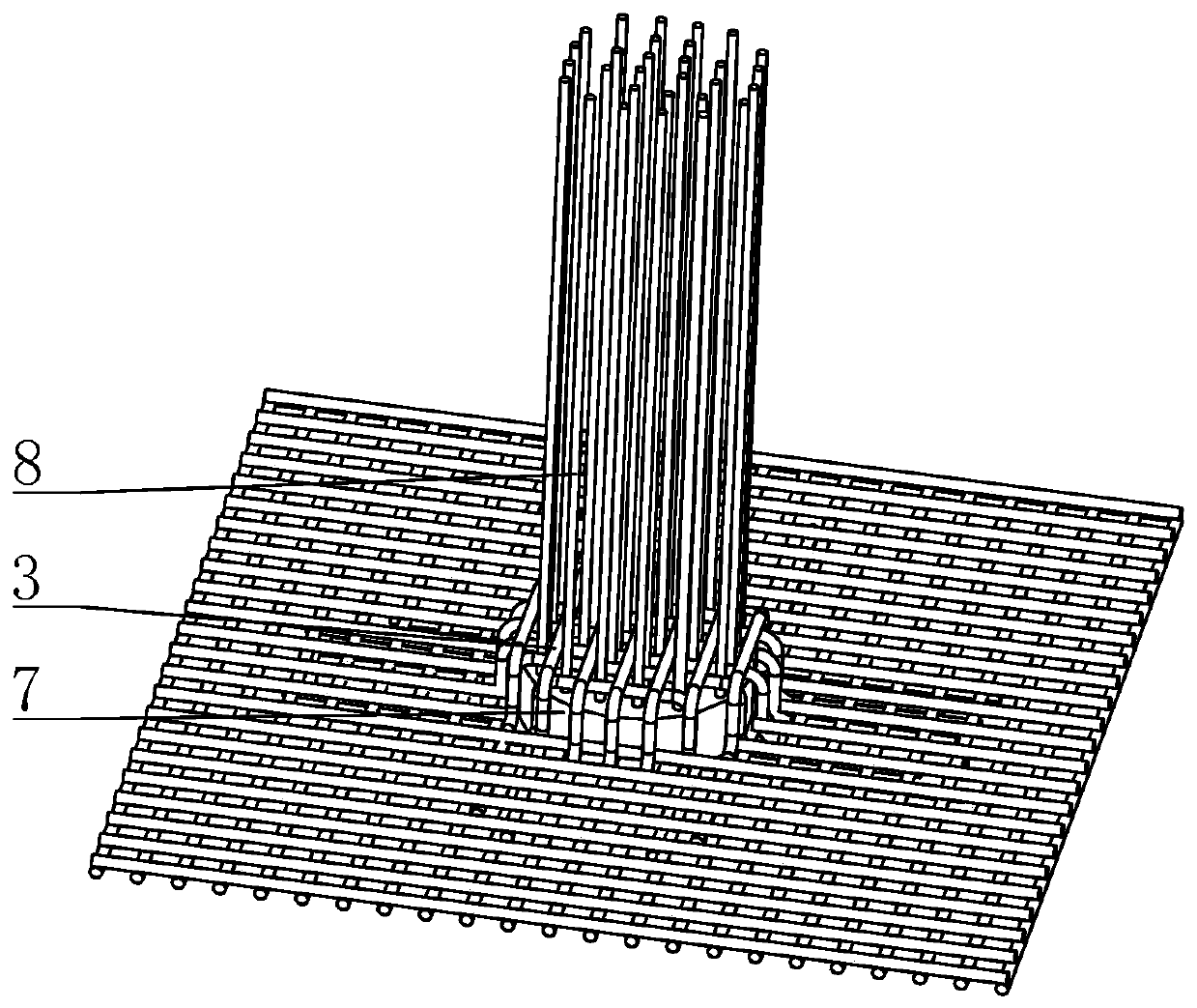
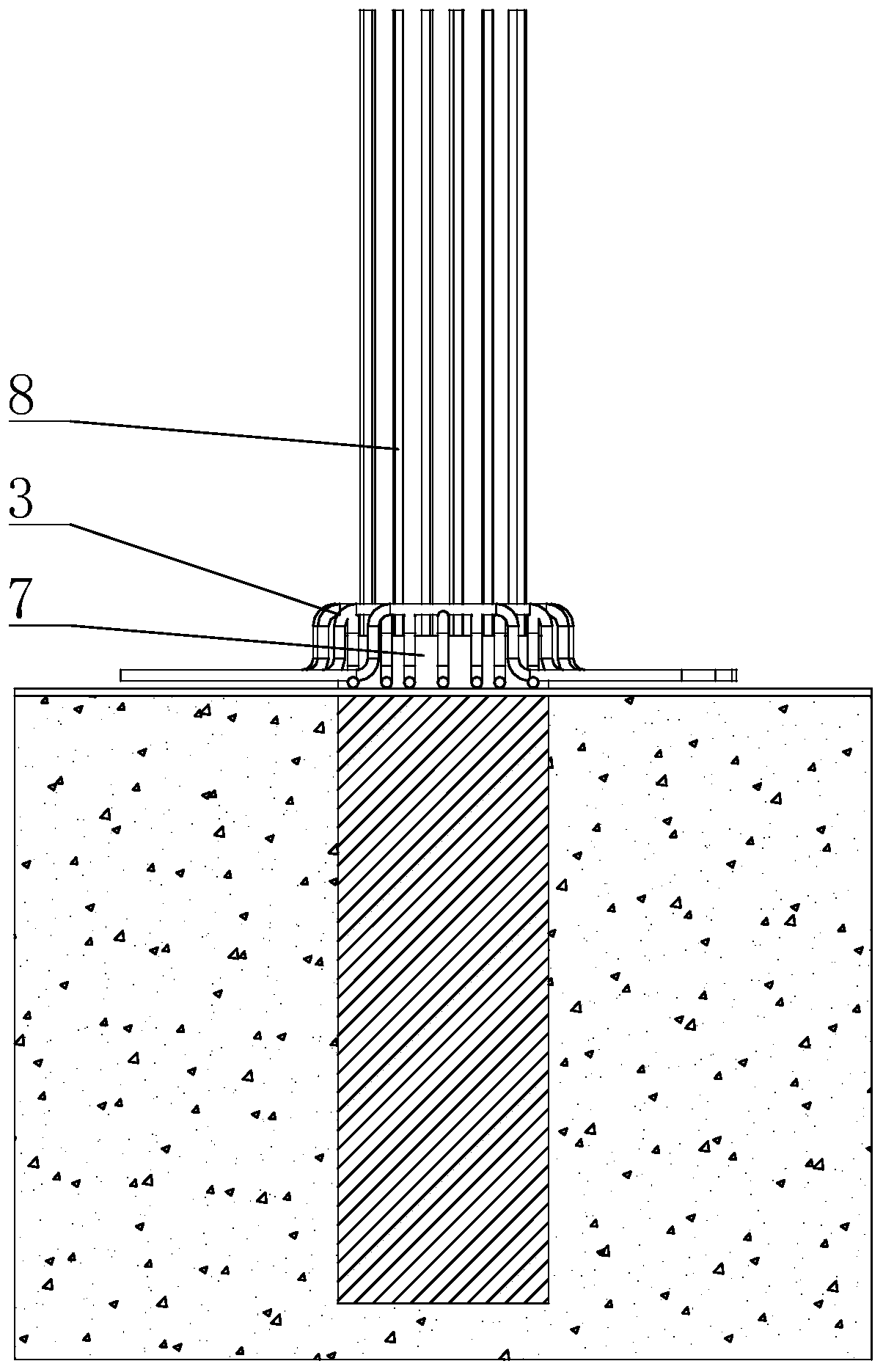
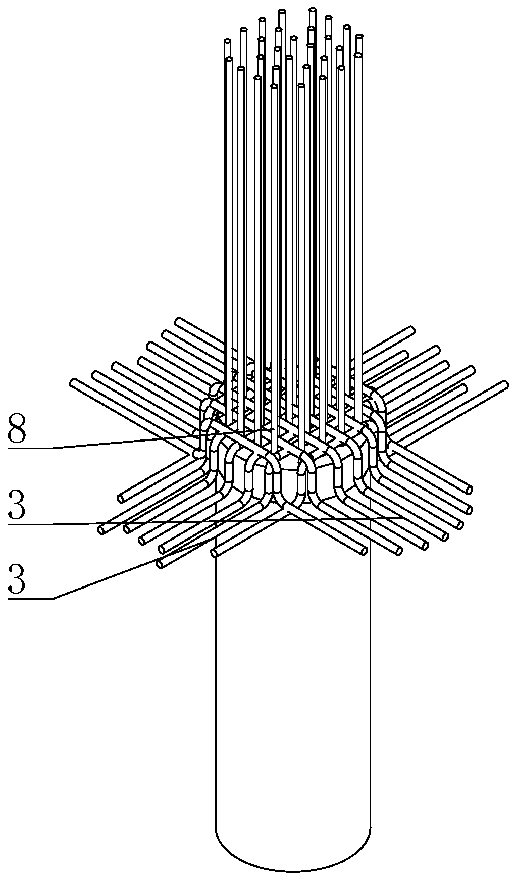
[0043] The present invention provides a bridge pile foundation pile head grouting connection steel bar structure and construction method thereof, aiming at setting a more fitting steel bar structure around the concrete pile head 7, so that the connection between the pile head and the steel bar on the bridge is safer and more reliable.

[0044] Specifically, combined with the fi...


PUM


Abstract

The invention provides a bridge pile foundation pile head pouring connection steel bar structure and a construction method thereof. A bent structure matched with the longitudinal section of a concretepile head is formed by arranging n-shaped steel bars and connecting the two ends of an upper connecting part of each steel bar with a lower connecting part through side edge parts; the upper connecting parts of the multiple steel bars are matched with different chord lengths of the cross section of the concrete pile head; and a cover body frame structure matched with the concrete pile head is formed through positioning arrangement of the steel bars and the concrete pile head and binding. According to the bridge pile foundation pile head pouring connection steel bar structure and the construction method thereof, the steel bars and the concrete pile head are positioned, the cover body frame structure matched with the concrete pile head is formed through binding, construction of a peripheralframe of the concrete pile head is achieved, the periphery of the concrete pile head is supported by tight steel bars, the connecting position of a steel bar body of a bridge and the concrete pile head is firmer, the connecting strength of a pile foundation and a bridge body is greatly improved, and safety is higher.

Description

technical field [0001] The invention relates to the technical field of construction auxiliary equipment, in particular to a bridge pile foundation pile head filling connection steel bar structure and a construction method thereof. Background technique [0002] At present, the construction of cast-in-situ concrete piles has been widely used in bridge construction. After the construction of cast-in-situ piles, the pile heads need to be removed. Generally, large-scale machinery must not be used to remove the pile head concrete protruding from the ground, and then bonded to the main beam body of the bridge. Pile head concrete is usually driven by an air compressor, and the concrete is broken by a manual pneumatic pick. After the conventional concrete pouring pile is broken, there will be a concrete pile head protruding from the foundation (cylindrical table shape) and an axial support frame steel bar (straight strip extending upward), but due to the limitation of the cylindrical...

Claims


Application Information

Patent Timeline
Patent Type & Authority Applications(China)
IPC IPC(8): E02D27/12E02D27/52E02D5/34E01D21/00
CPCE01D21/00E02D5/34E02D27/12
Inventor 岳跃稳刘森林刘成功许玉勇钮玉亭江涛杨文超戴志彪陈德生左明
Owner 安徽建工路港建设集团有限公司
Why Eureka
Try Eureka